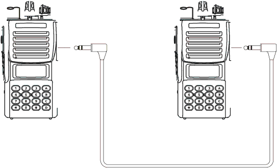
Vertex Standard VX-410 service manual Cloning

Page 7

Cloning

The VX-410/-420series includes a convenient Cloning feature, which allows the programming data from one trans- ceiver to be transferred to another VX-410/-420series. Here is the procedure for Cloning one radio's data to another.

1.Turn both transceivers off.

2.Remove the plastic cap and its two mounting screws from the MIC/SP jack on the right side of the trans- ceiver. Do this for both transceivers.

3.Connect the optional CT-27cloning cable between the MIC/SP jacks of the two transceivers.

4.Press and hold in the PTT and Soft key assigned to “MONITOR” while turning the transceiver on. Do this for both transceivers (the order of the switch-on does not matter). “CLONE” will appear on the displays (for the VX-420series) of both transceivers when Clone mode is successfully activated in this step; in the case of the VX-410series, no change will be observed at this point.

5.On the Destination transceiver, press the Soft key as- signed to “MONITOR”. “LOADING” will appear on the LCD (for VX-420series; for VX-410series, the TX/ BUSY indicator on the top of the radio will glow Green).

6.Press the PTT switch on the source transceiver; “SEND- ING” will appear on the Source transceiver (for VX- 420 series; for VX-410series, the TX/BUSY indica- tor on the top of the radio will glow Red), and the data will be transferred.

7.If there is a problem during the cloning process, “ER- ROR” will appear on the LCD (for VX-420series; for VX-410series, the TX/BUSY indicator on the top of the radio will blink Red); check your cable connec- tions and battery voltage, and try again.

8.If the data transfer is successful, the display will return to “CLONE” (for VX-420series; for VX-410series, the TX/BUSY indicator on the top of the radio will turn off). Turn both transceivers off and disconnect the CT-27cable. You can then turn the transceivers back on, and begin normal operation.

9.Replace the plastic cap and its two mounting screws.

Optional Cloning Cable CT-27

7

Image 7
Contents UHF FM Transceiver ContentsLow Battery Indication Battery Pack Installation and RemovalOperating Manual Reprint Operation Quick Start Preliminary Steps Lock Low Power Monitor Squelch OffTalk Around Call 1, 2, 3/ResetFollow-Me Scan Dual WatchREC/PLAY Voice Storage Option EmergencyGroup ACC 1Cloning General Specifications SpecificationsFront Case Assy Exploded View & Miscellaneous PartsPage Block Diagram Page Squelch Control Receive Signal PathTransmit Signal Path Circuit DescriptionPLL Frequency Synthesizer Automatic Transmit Power ControlTransmit Inhibit Spurious SuppressionRequired Test Equipment Alignment Preparation & PrecautionsAlignment IntroductionAlignment tool outline MAX Deviation Transmitter Output PowerPLL VCV Varactor Control Voltage Reference FrequencyDtmf Deviation Ctcss DeviationMAX Ref Deviation STD DeviationMain Unit Circuit DiagramPage Side a Parts LayoutRD07MVS1 Side BParts List TESVA1C105M1-8R TEMSVA0J475M-8R GRM36CH820J50PT LED Transistor UMX1N TN RMC1/8 R33KTP 16W RMC1/16S 102JTH J24189025 1084 100k 16W RMC1/16S 102JTH J24189025 1220 Rotary Switch Dummy Unit Circuit Diagram Parts Layout Parts ListFVP-25 Encryption / Dtmf Pager Unit GRM39CH100D50PT VTP-50 VX-Trunk Unit Description Value TOL MFR’S Desig Vxstd P/N Vers LOT Side DVS-5 Voice Storage Unit GRM36CH680J50PT 0 5 0 U 9 0 a