Kawasaki 840700 instruction manual Parts List Parts Diagram, Description QTY

Page 13


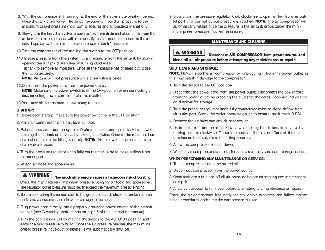
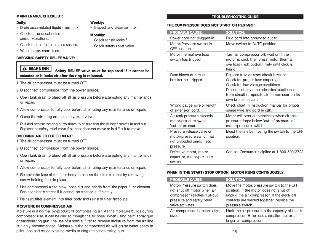
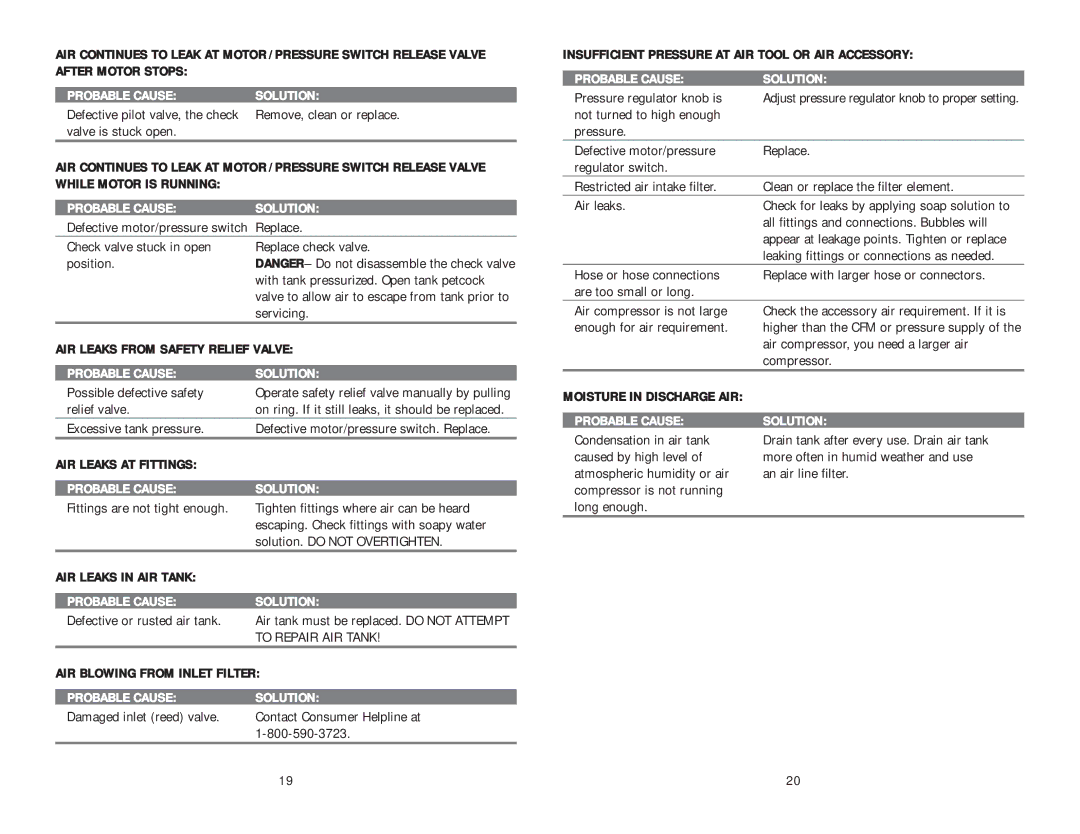
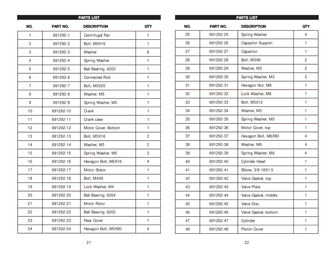
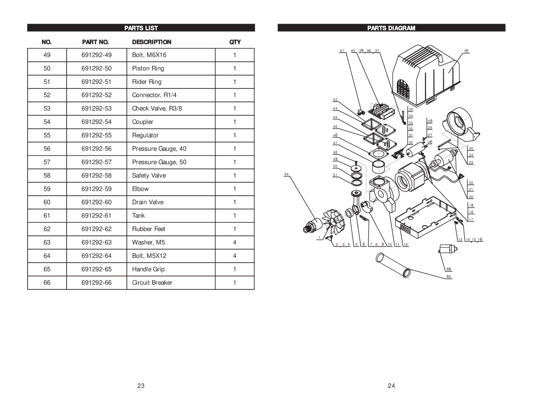
PARTS LIST


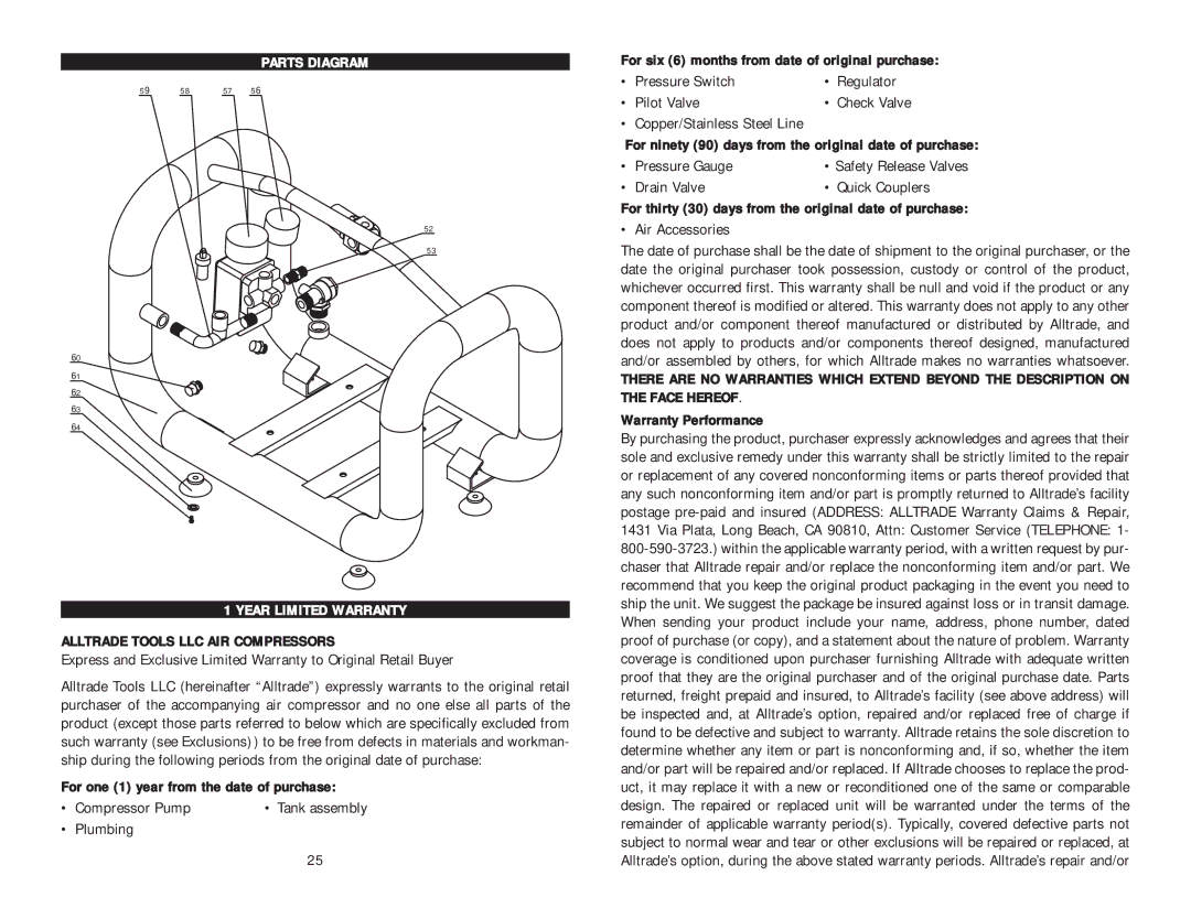
PARTS DIAGRAM

NO.

PART NO.

DESCRIPTION

QTY

49

691292-49

Bolt, M6X16

1


41

40

39

38

37


50

691292-50

Piston Ring

1


51

691292-51

Rider Ring

1


52

691292-52

Connector, R1/4

1


42


53

691292-53

Check Valve, R3/8

1


43


54

691292-54

Coupler

1


44


45


55

691292-55

Regulator

1


46


56

691292-56

Pressure Gauge, 40

1


47


48


57

691292-57

Pressure Gauge, 50

1


49


50


58

691292-58

Safety Valve

1


54

51


59

691292-59

Elbow

1


60

691292-60

Drain Valve

1


61

691292-61

Tank

1


62

691292-62

Rubber Feet

1


63

691292-63

Washer, M5

4


1


2 3

4

5 6

7

8 9 10 11 12

64

691292-64

Bolt, M5X12

4


65

691292-65

Handle Grip

1


66

691292-66

Circuit Breaker

1


36

35

34

33 29

3228

3127

30 26

25

24

23

22

21

20

19

18

17

13 14 15 16

66

65

23

24

Image 13
Contents Gallon AIR Compressor 2 Peak HP Specifications Table of ContentsSafety Alert CongratulationsSafety Warnings Recognize Safety SYMBOLS, Words and LabelsRead ALL Safety Warnings Before Using AIR Compressor General Safety WarningsAfter Handling ING Vapors and DUST. Wash Hands After UsingDrain Liquid from AIR Tank Daily Risk of Fire or ExplosionInstallation and Location Extension Cords Grounding InstructionsExtension Cord Length Compressor FeaturesControls and Components Initial Setup / BREAK-IN Procedure Compressor FeaturesOperating the AIR Compressor When Performing ANY Maintenance or Service Maintenance and CleaningStartup Shutdown and Storage Probable Cause Solution Troubleshooting GuideInsufficient Pressure AT AIR Tool or AIR Accessory AIR Leaks from Safety Relief ValveAIR Leaks AT Fittings AIR Leaks in AIR TankDescription Parts ListDescription QTY Parts List Parts DiagramAlltrade Tools LLC AIR Compressors Year Limited WarrantyLimitations on Warranty Disclaimers Warranty DisclaimersExclusions Limitation Of Liability