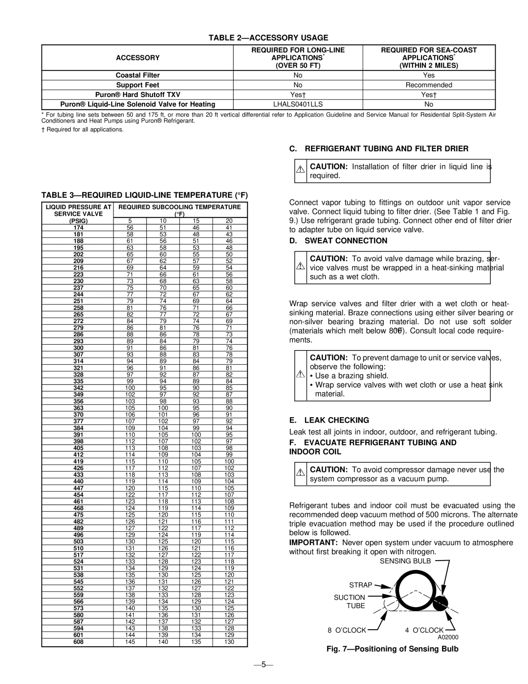
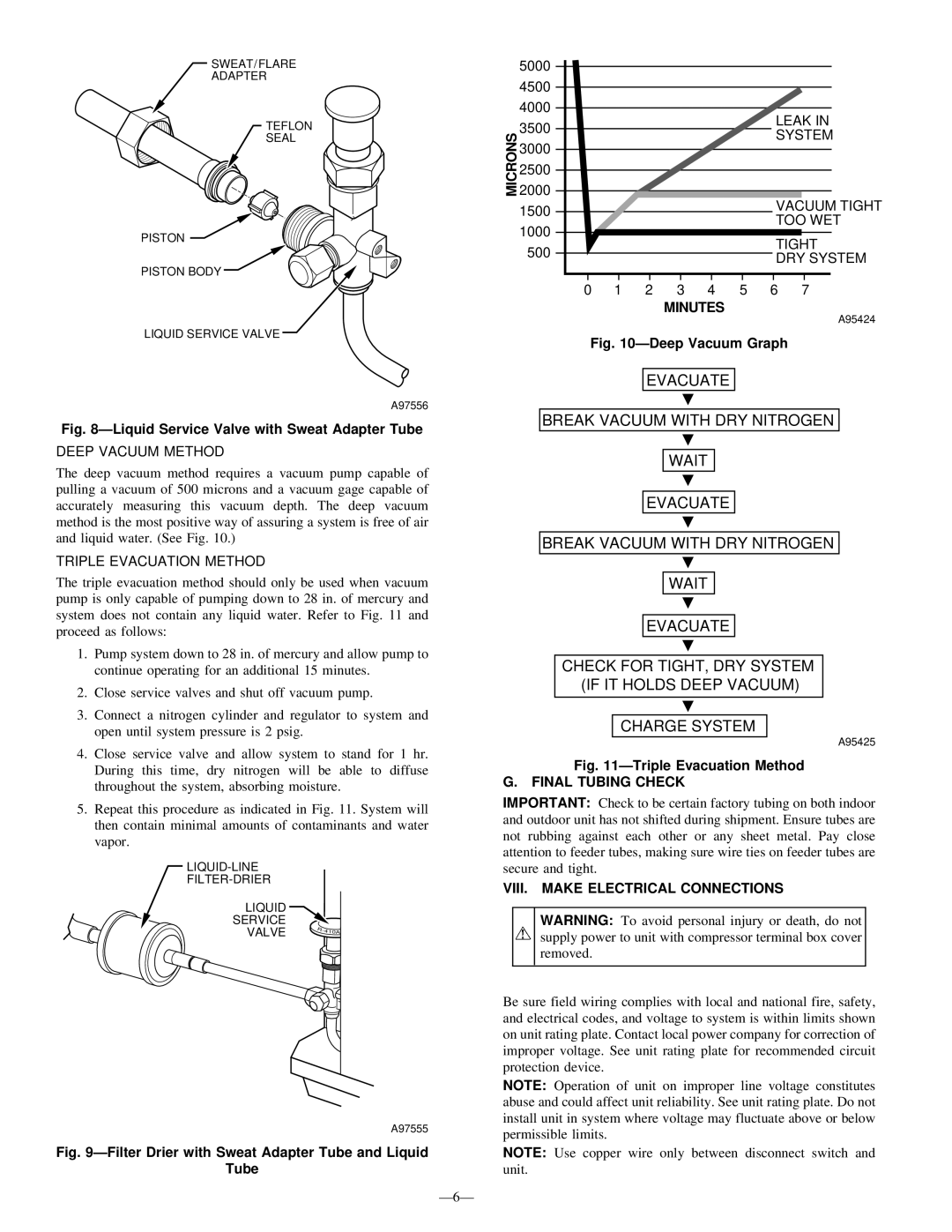
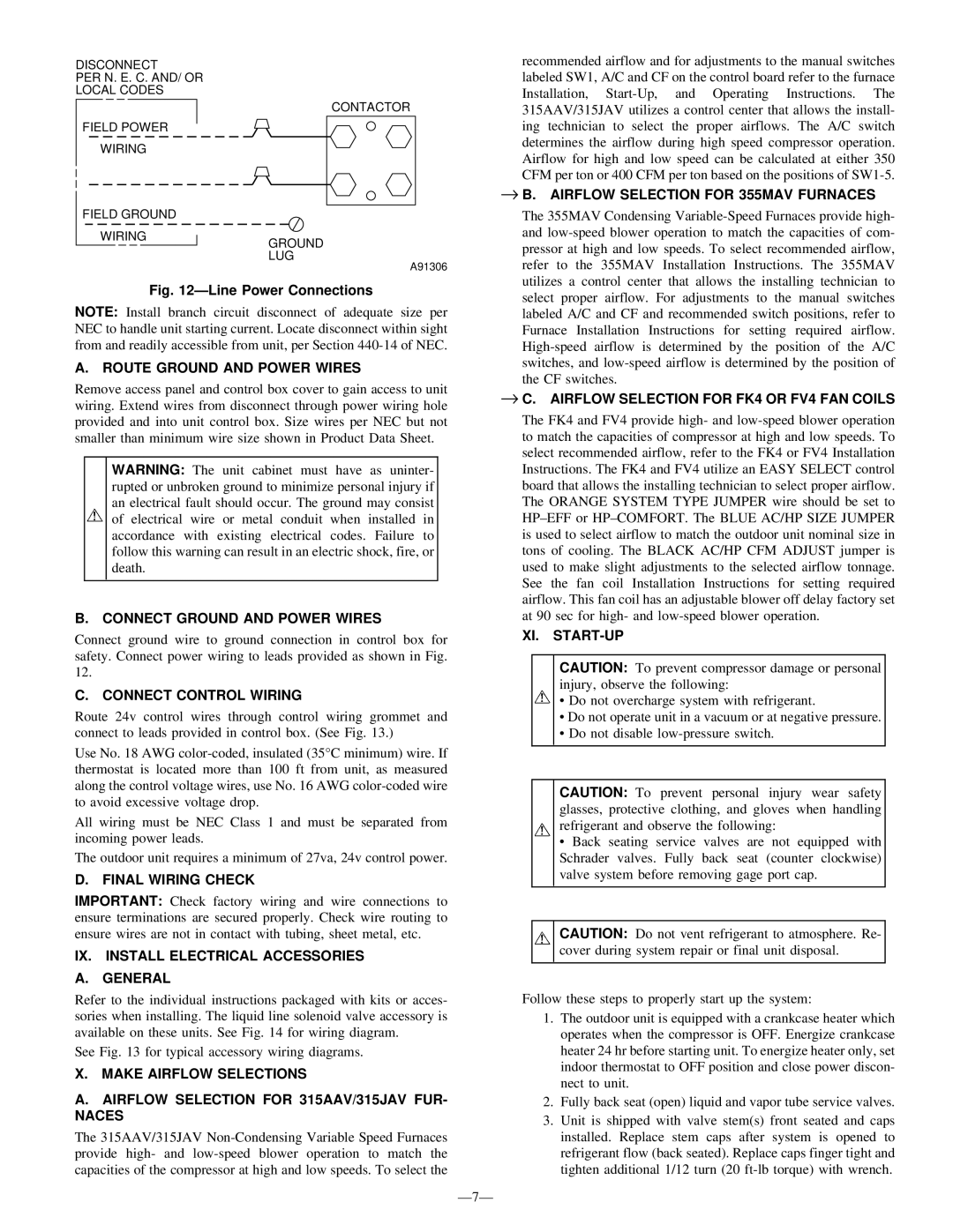
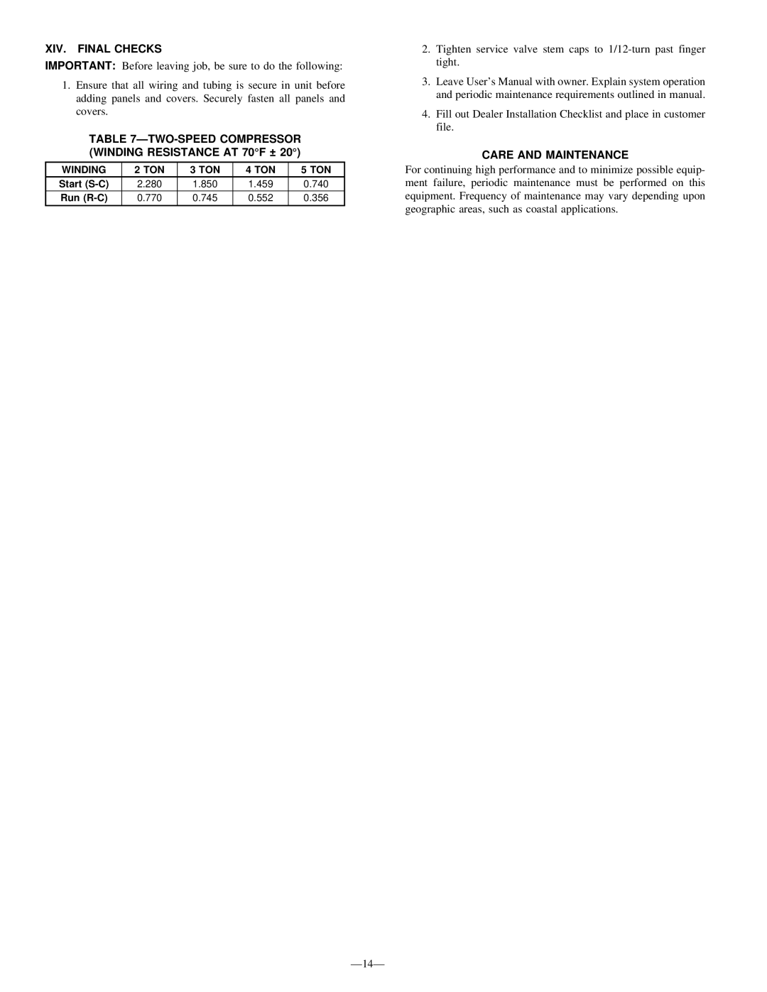
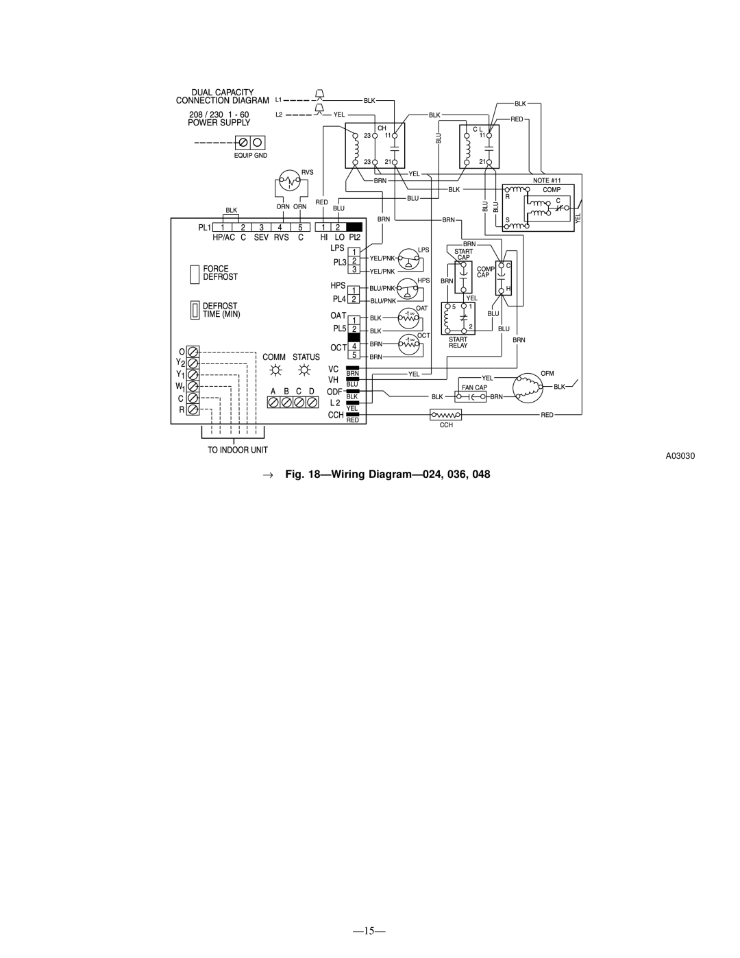
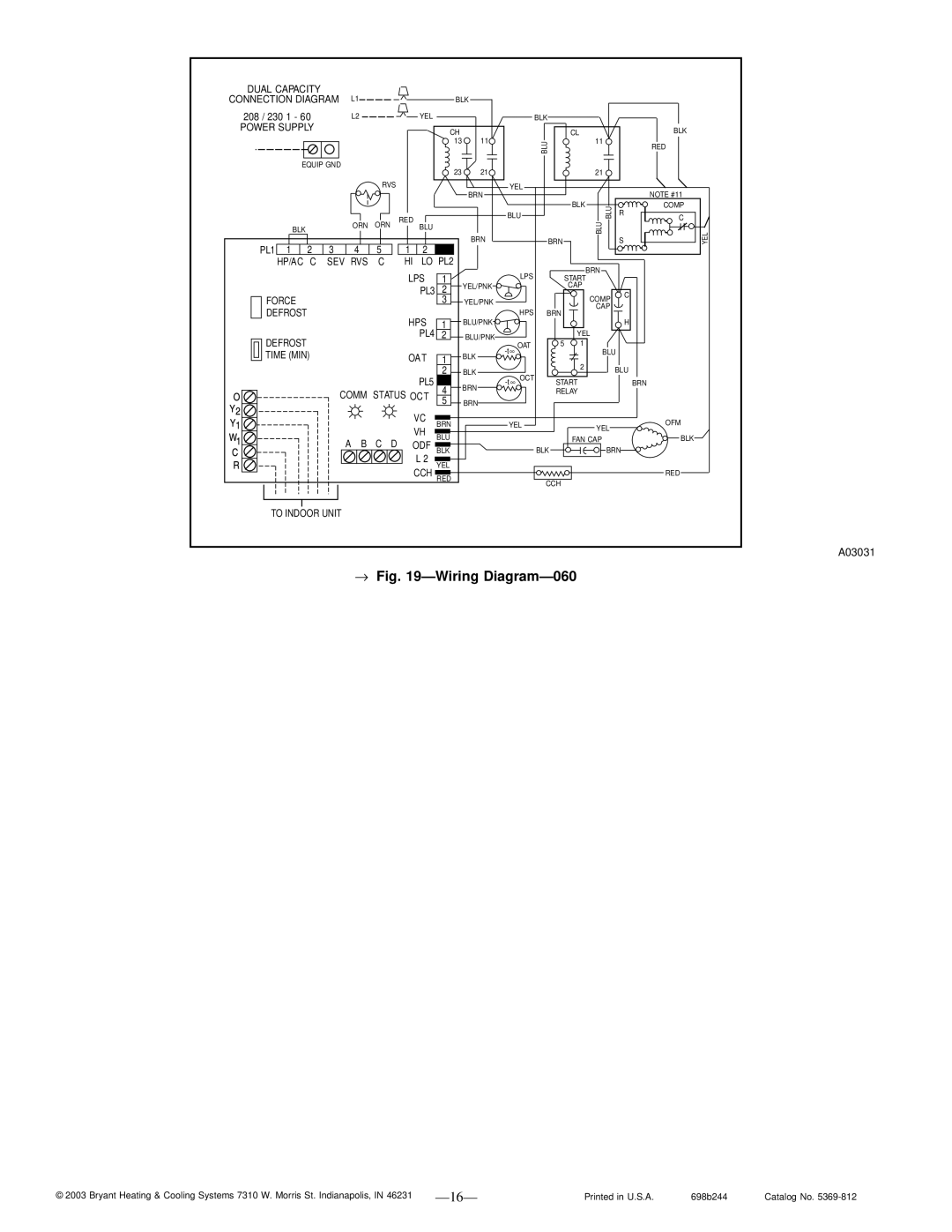
Bryant 698B instruction manual Wiring Diagram Notes, XII. Check Charge Unit Charge

Page 10

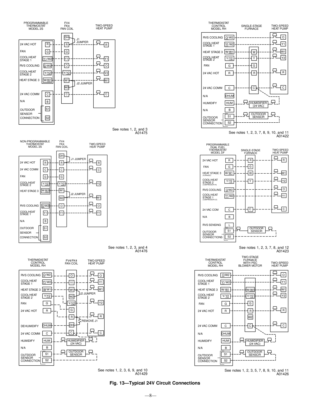
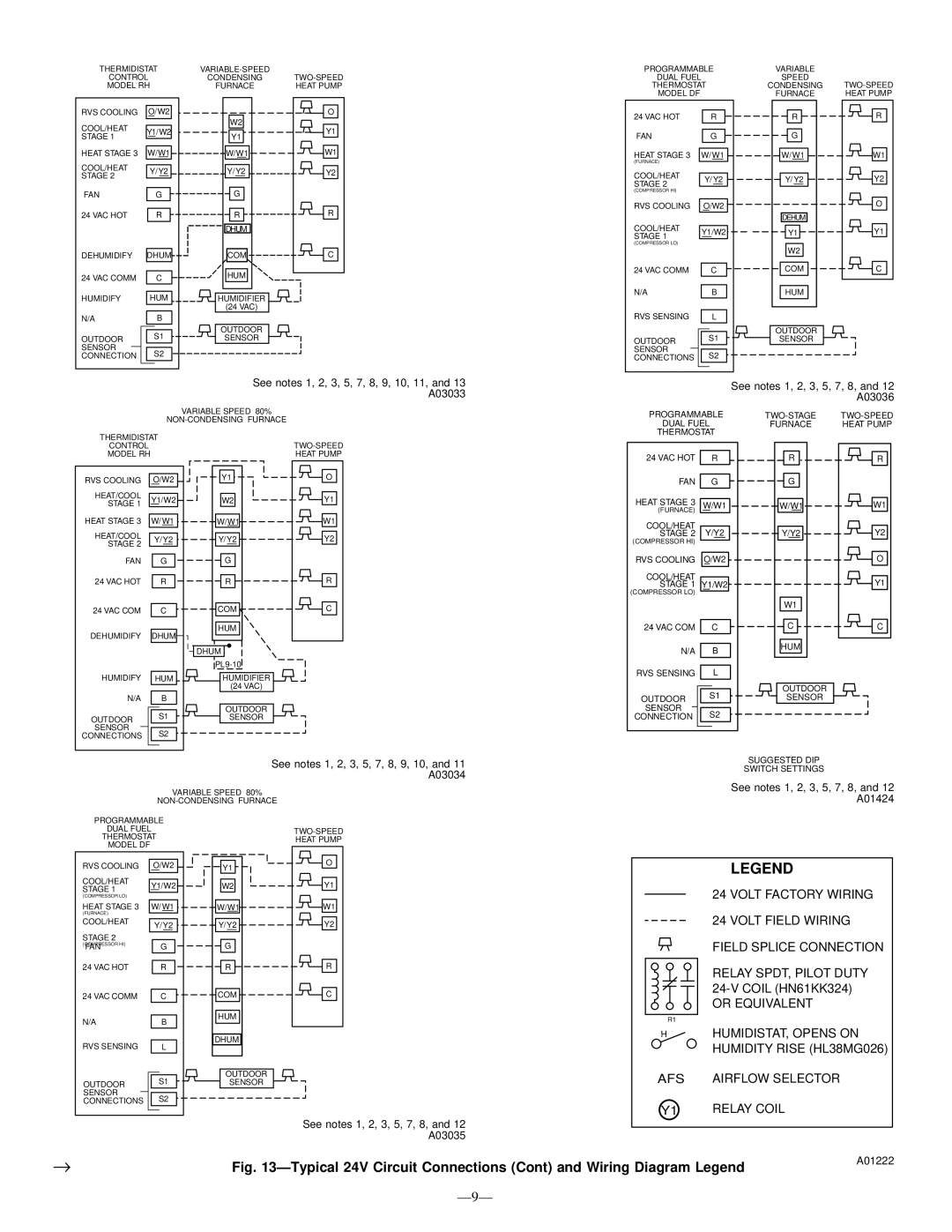
WIRING DIAGRAM NOTES:

1.Wiring must conform to NEC or local codes.

2.Underlined letter on thermostat terminal indicates its usage. For example: O/W2 means O is energized in cooling mode.

3.Refer to indoor unit Installation Instructions for any additional features and wiring information.

4.Non-Programmable Model 2S01–B, when used in heat pump installations (jumper R19 NOT cut), uses O/W2 to control reversing valve.

5.Furnace must control its own second-stage operation via furnace control algorithms. Refer to furnace Installation Instructions for proper setup.

6.To activate dehumidify function on FK4 or FV4, remove J1 jumper at fan coil control board.

7.Heat pump MUST have a high-pressure switch for dual fuel applications.

8.Outdoor air temperature sensor must be attached in all dual fuel applications.

9.Thermidistat Dip Switch No. 1 should be set in ON position for heat pump installations.

10.Thermidistat Dip Switch No. 2 should be set in the ON position for dual capacity compressor operation.

11.Thermidistat Configuration Option No. 10 “Dual Fuel Selection” must be turned ON in all dual fuel applications.

12.Dual Fuel Dip Switch–D (no. 4) must be set in the ON position for dual capacity compressor operation.

13.The DE jumper located next to the DHUM terminal must be removed to enable the DEHUM input.

NOTE: If unit has not operated within the past 12 hr or following a unit power-up, upon the next thermostat high- or low-speed demand, unit operates for a minimum of 5 minutes on high speed.

4.Close electrical disconnects to energize system.

5.Set room thermostat at desired temperature. Be sure the set point is below indoor ambient and is set low enough to energize desired speed.

6.Set room thermostat to COOL or HEAT and fan control to AUTO or ON as desired. Wait for appropriate time delay(s). Operate unit for 15 minutes. Check refrigerant charge.

NOTE: Bryant electronic thermostats are equipped with a 15 minute staging timer. This timer prevents the dual capacity system from operating at high capacity until unit has been operating in low capacity for 15 minutes unless there is at least a 5°F difference between room temperature and thermostat set point. To force high capacity, adjust the set point at least 5° below room ambient for cooling or 5° above room ambient for heating.

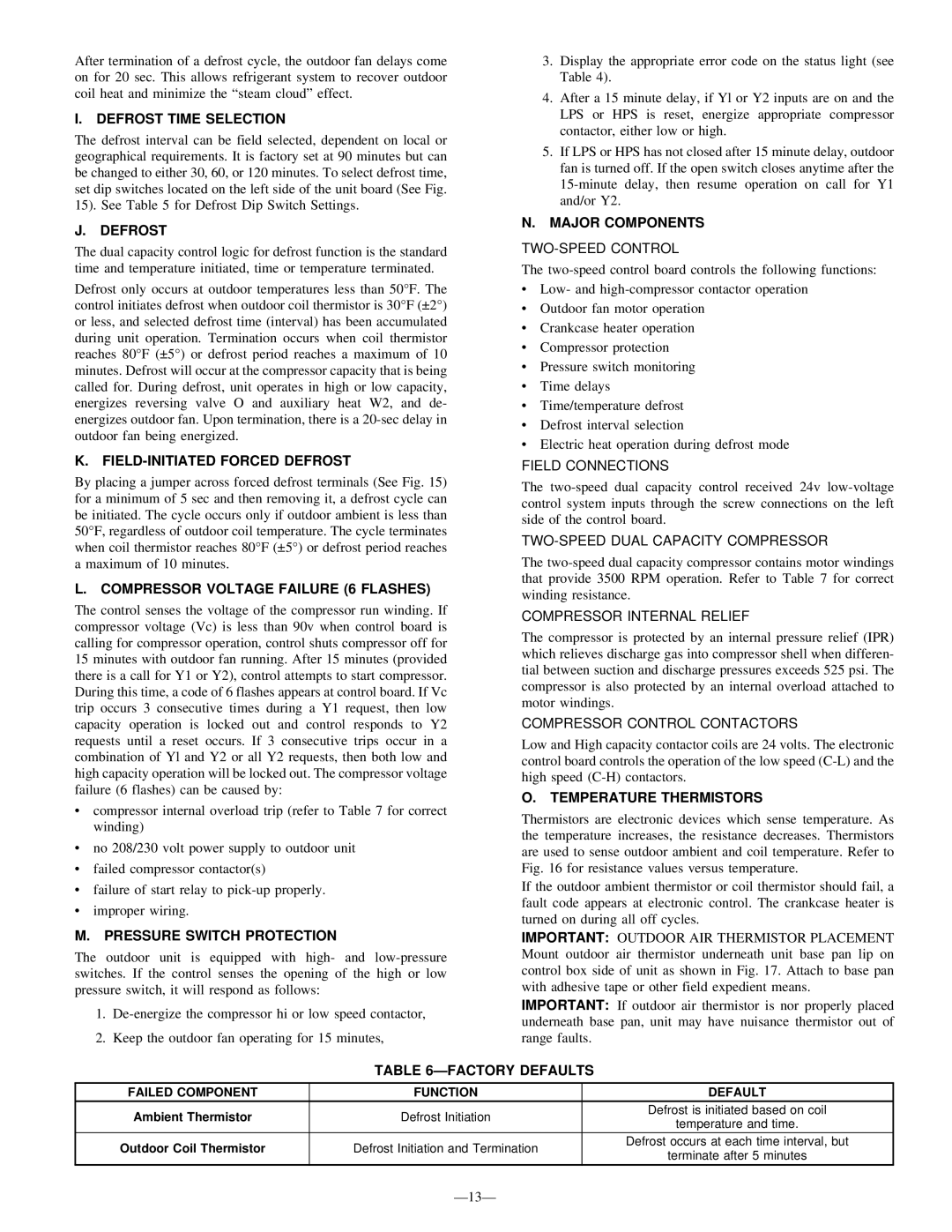
XII. CHECK CHARGE

WARNING: Service valve gage ports are not equipped with Schrader valves. To prevent personal injury, make sure gage manifold is connected to the valve gage ports before moving valves off fully back seated position. Wear safety glasses and gloves when handling refrigerant.

A. UNIT CHARGE

Factory charge is shown on unit rating plate. To check charge in cooling mode, refer to Cooling Only Procedure. To charge in heating mode, weigh the charge in.

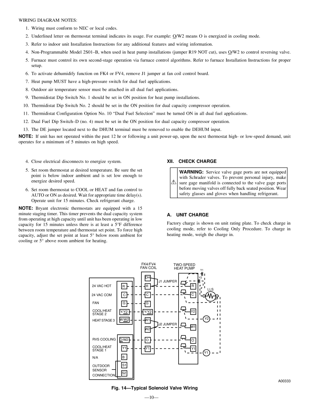
FK4/FV4

TWO-SPEED


FAN COIL

HEAT PUMP

Y1


DH


24 VAC HOT


R


R


24 VAC COM


C


C


FAN


G


G


COOL/HEAT


Y/Y2


Y/Y2


STAGE 2


HEAT STAGE 3


W/W2


W1


W2


RVS COOLING


O/W2


O


COOL/HEAT


Y1


Y1


STAGE 1


N/A


B


OUTDOOR


S1


SENSOR


CONNECTION


S2


J1 JUMPER

J2 JUMPER

Y2

R

LLS

C

Y2

Y2

W1

O

Y1

Y1

A00333

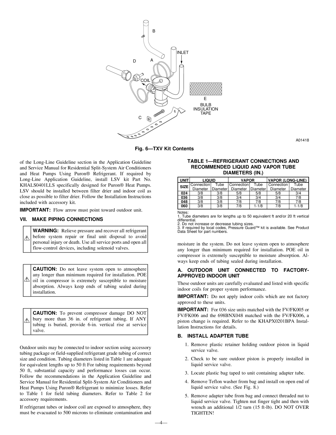
Fig. 14—Typical Solenoid Valve Wiring

—10—

Image 10
Contents Safety Considerations Installation RecommendationsInspect Equipment Installation Check Equipment and JOB Site Unpack UnitII. Install on a SOLID, Level Mounting PAD III. Clearance RequirementsVI. Check Indoor Expansion Device Furnace Coils FAN CoilsVII. Make Piping Connections Install Adapter TubeOutdoor Unit Connected to FACTORY- Approved Indoor Unit Refrigerant Tubing and Filter Drier Accessory UsageRequired LIQUID-LINE Temperature F Sweat ConnectionFinal Tubing Check MinutesVIII. Make Electrical Connections Connect Control Wiring Route Ground and Power WiresConnect Ground and Power Wires Final Wiring CheckTypical 24V Circuit Connections Volt Factory Wiring Wiring Diagram Notes XII. Check Charge Unit ChargeXIII. System Functions and Sequence of OP- Eration Cooling only ProcedureHeating Check Charge Procedure Cooling OperationDefrost DIP Switch Settings ONE Minute Speed Change Time DelayFactory Defaults Heating OperationDefrost Time Selection Pressure Switch ProtectionTemperature Thermistors DefrostXIV. Final Checks Care and MaintenanceTWO-SPEED Compressor Winding Resistance AT 70F ± → -Wiring Diagram-024, 036 Wiring Diagram-060
Related manuals
Manual 44 pages 15.83 Kb

698B specifications

The Bryant 698B is an advanced residential air conditioning unit known for its efficiency and reliability in delivering optimal indoor climate control. Designed for comfort and energy savings, the Bryant 698B is a notable choice for homeowners seeking high-performance cooling solutions.

One of its standout features is its impressive Seasonal Energy Efficiency Ratio (SEER) rating, which ranges from 16 to 18, depending on the specific model. This high efficiency helps to reduce energy consumption while providing consistent cooling performance, allowing homeowners to enjoy a comfortable environment without incurring high electricity bills. The unit's efficient operation is recognized by various energy efficiency certifications, helping promote a more sustainable lifestyle.

The Bryant 698B is equipped with a variable-speed compressor, which adjusts its operating speed based on the cooling needs of the home. This technology allows the system to run at lower speeds for longer periods, ensuring a more consistent temperature throughout the space and reducing wear and tear on the system. This also minimizes noise levels, making the Bryant 698B one of the quieter units available today.

In terms of build quality, the Bryant 698B features a durable steel cabinet designed to withstand harsh weather conditions. The unit is treated with a baked-on powder finish that provides corrosion resistance, ensuring its longevity even in challenging environments. Additionally, the coil is designed for easy maintenance, allowing for optimal airflow and ensuring the system runs efficiently.

Smart technology integration is another highlight of the Bryant 698B. The unit can be connected to a smart thermostat, offering homeowners remote access to control their HVAC system from their smartphones. This capability allows for more precise temperature adjustments and scheduling, contributing to enhanced energy savings and increased comfort.

The Bryant 698B also offers various customizable options, including different cooling capacities and compatibility with additional heating systems like heat pumps or gas furnaces. This versatility makes it suitable for a wide range of residential applications.

In summary, the Bryant 698B air conditioning unit stands out due to its energy efficiency, variable-speed compressor, durable construction, smart technology features, and customization options, making it an ideal choice for homeowners looking for a robust and efficient cooling solution.