RIDGID R2611 Attaching the Dust BAG, Attaching the Sander to a Vacuum, Turning the Sander ON/OFF

Page 12

OPERATION

ATTACHING THE DUST BAG
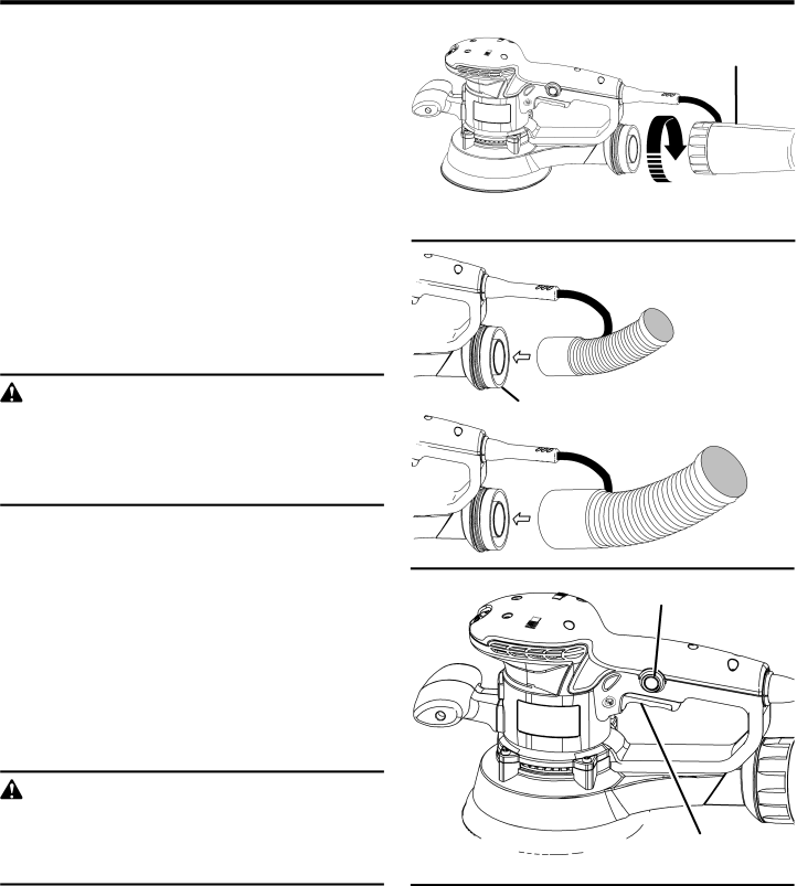
See Figure 6.

The dust bag provides a dust collection system for the sander. Sanding dust is drawn up through the holes of the sanding disc and collected in the dust bag during sanding.

To attach the dust bag:

Unplug the sander.

Slide dust bag assembly onto blower exhaust turning clockwise to tighten.

ATTACHING THE SANDER TO A VACUUM

See Figure 7.

To attach the sander to a vacuum:

DUST BAG

Fig. 6

1-1/4 in. VACUUM HOSE

Unplug the sander.

Turn the dust bag counterclockwise to remove from sander.

Attach the vacuum hose to the vacuum adaptor.

WARNING

When sander is not connected to vacuum, always install dust bag back on sander. Failure to do so could cause sanding dust or foreign objects to be thrown into the face or eyes which could result in possible serious injury.

NOTE: A standard 1-1/4 in. vacuum hose fits inside the smaller diameter hole inside the dust exhaust, while a stan- dard 2-1/2 in. vacuum hose connection fits inside the larger hole of the dust exhaust.

1-1/4"

VACUUM ADAPTOR

2-1/2"

2-1/2 in. VACUUM HOSE

Fig. 7

TURNING THE SANDER ON/OFF

See Figure 8.

Depress the switch trigger to turn the sander ON. Release the switch trigger to turn the sander OFF.

LOCKING ON THE SANDER

See Figure 8.

The sander is equipped with a lock-on feature, which is convenient for continuous sanding for extended periods of time.

WARNING:

Before connecting the sander to a power supply, make sure it is not in the locked-on position. Failure to do so could result in accidental starting of the tool resulting in serious injury.

To lock on the sander:

Depress the switch trigger.

Push in the lock-on button.

Release the switch trigger.

Release the lock-on button.

NOTE: To release the lock, depress the switch trigger.

LOCK-ON BUTTON

SWITCH TRIGGER

Fig. 8

If you have the lock-on feature engaged during use and the sander is accidentally disconnected from the power supply, disengage the lock-on feature immediately. Also, do not lock the switch trigger if you might need to suddenly stop the sander.

12

Image 12
Contents OPERATOR’S Manual Double Insulated Variable SpeedTable of Contents IntroductionGeneral Safety Rules Work Area SafetyElectrical Safety Personal SafetySpecific Safety Rules ServiceSymbols Symbol Name DESIGNATION/EXPLANATIONSymbol Signal Meaning Electrical Double InsulationElectrical Connection Extension CordsFeatures Product SpecificationsAssembly Operation ApplicationsAttaching the Front Handle Sanding Disc SelectionAttaching Hook and Loop Sanding Disc Selecting the Orbit DiameterAttaching the Dust BAG Attaching the Sander to a VacuumTurning the Sander ON/OFF Locking on the SanderOperating the Sander Emptying the Dust BAGMaintenance Brush ReplacementGeneral Maintenance LubricationWarranty DAY Satisfaction Guarantee PolicyWhat is Covered Under the 3 Year Limited Service Warranty HOW to Obtain Service What is not CoveredCustomer Service Information