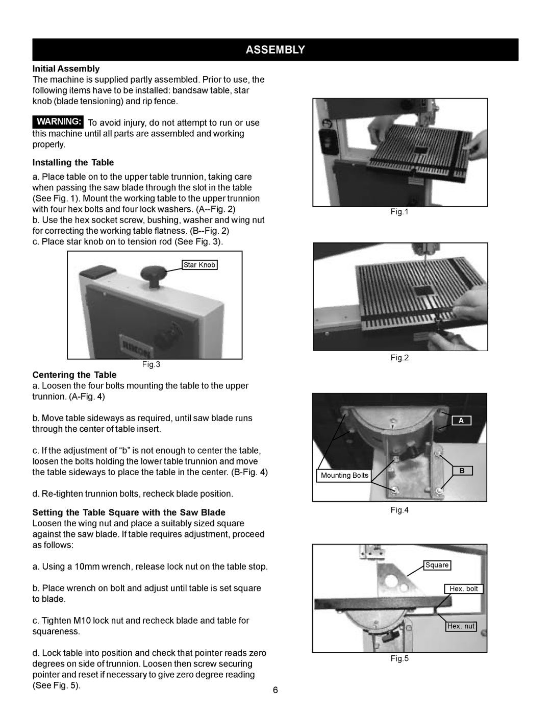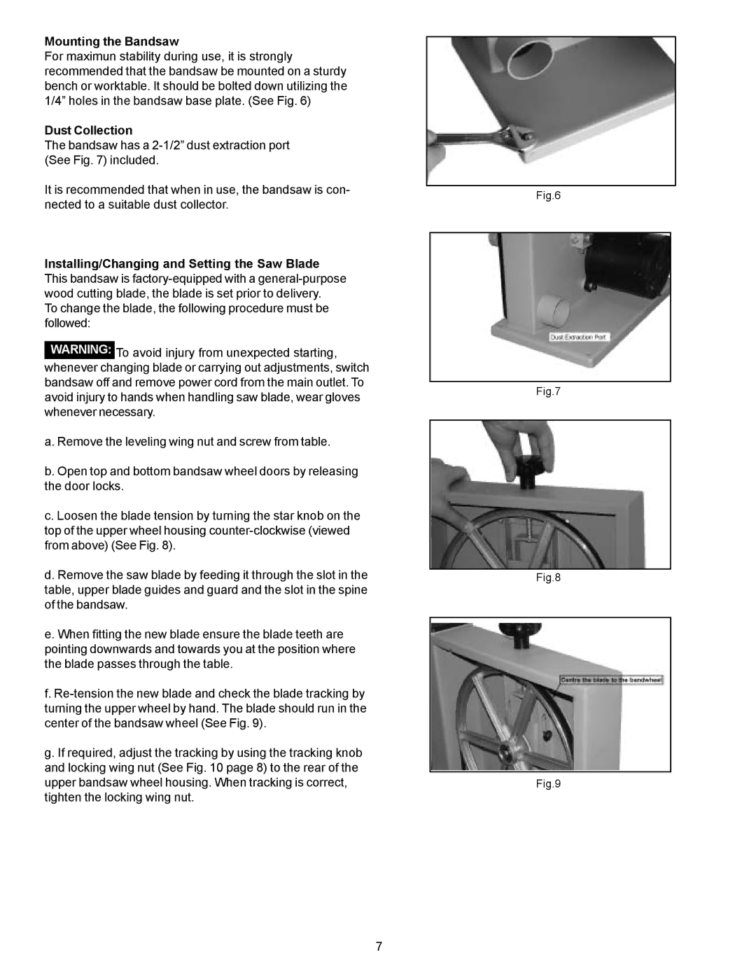
Installing/Changing and Setting the Saw Blade Cont. h. Replace leveling wing nut and screw to table.
i. Close and lock both bandsaw wheel doors before recon- necting the power supply.
Tracking the Bandsaw Blade
Set the tracking of the blade before setting the blade guides. Once the blade is installed and tensioned, track the blade by adjusting the tracking knob by hand (See Fig. 10). The blade should run in the center of the bandsaw wheel as shown in (See fig. 9). When the correct adjustment is achieved lock the tracking knob with the wing nut. (See Fig. 10)
Adjusting the Blade Guides
The saw blade guides of this bandsaw ensure exact blade position for clean cuts. When using narrow blades, ensure that the upper and lower blade guides positively support the blade from both sides and the rear (See Fig. 11).
Set the bearings of the upper and lower blade guides to within approximately 1/64” of the blade. Adjust the rear upper and lower thrust bearings to the back of the blade. Position the thrust bearings so they do not spin while blade is moving, only when pressure is applied to the blade during cutting operation (See Fig. 12).
NOTE: Do not set bearings too close, as resulting friction generates heat, which may have an adverse effect on the bearings and the saw blade as well.
Setting the Cutting Height
a. The upper blade guide should always be set approxi- mately 1/4” above the workpiece.
b. To adjust, loosen the wing nut at the side of the upper wheel housing (See Fig. 13).
c. Set the blade guide to the required height by raising or lowering the blade guard by hand.
d. Tighten wing nut after proper height is set (See Fig. 13).
Tilting the Bandsaw Table
For bevel cuts, the bandsaw table tilts 0 through 45 degrees.
a. To tilt, loosen the wing nut on the table trunnion, set table to the required angle and tighten the wing nut again.
(See Fig. 14)
b. It is recommended to verify the correct angle setting using an angle guide, or by making trial cuts in scrap wood. Adjust the pointer accordingly by using a phillips head screwdriver.
Tracking Knob |
| Wing Nut |
Fig.10
Fig.11
Fig.12
Wing Nut
Fig.13
Wing Nut
Fig.14
8

