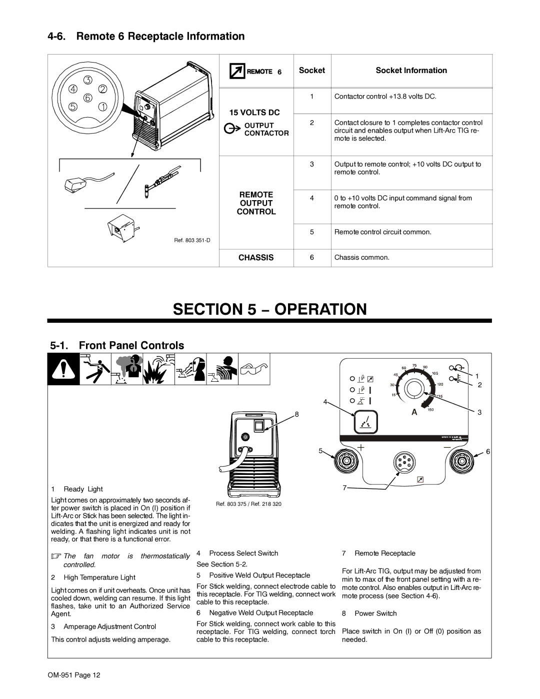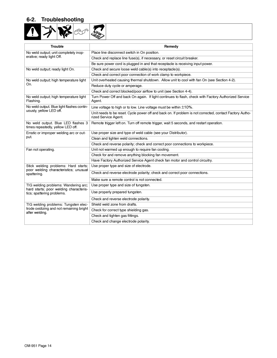
4-6. Remote 6 Receptacle Information
Ref. 803
6 | Socket | Socket Information | |
| 1 | Contactor control +13.8 volts DC. | |
15 VOLTS DC |
|
| |
OUTPUT | 2 | Contact closure to 1 completes contactor control | |
| circuit and enables output when | ||
CONTACTOR |
| ||
| mote is selected. | ||
|
| ||
| 3 | Output to remote control; +10 volts DC output to | |
|
| remote control. | |
REMOTE | 4 | 0 to +10 volts DC input command signal from | |
OUTPUT | |||
| remote control. | ||
CONTROL |
|
| |
| 5 | Remote control circuit common. | |
CHASSIS | 6 | Chassis common. |
SECTION 5 − OPERATION
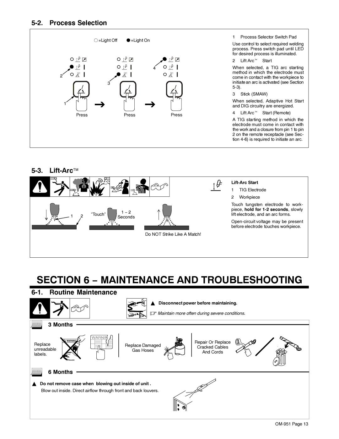
5-1. Front Panel Controls
1 Ready Light
Light comes on approximately two seconds af- ter power switch is placed in On (I) position if
4
8
5
Ref. 803 375 / Ref. 218 320
![]() 1
1
2
![]() 3
3
6
7![]()
![]()
.The fan motor is thermostatically controlled.
2 High Temperature Light
Light comes on if unit overheats. Once unit has cooled down, welding can resume. If this light flashes, take unit to an Authorized Service Agent.
3Amperage Adjustment Control This control adjusts welding amperage.
4Process Select Switch See Section
5Positive Weld Output Receptacle
For Stick welding, connect electrode cable to this receptacle. For TIG welding, connect work cable to this receptacle.
6 Negative Weld Output Receptacle
For Stick welding, connect work cable to this receptacle. For TIG welding, connect torch cable to this receptacle.
7 Remote Receptacle
For
8 Power Switch
Place switch in On (I) or Off (0) position as needed.
