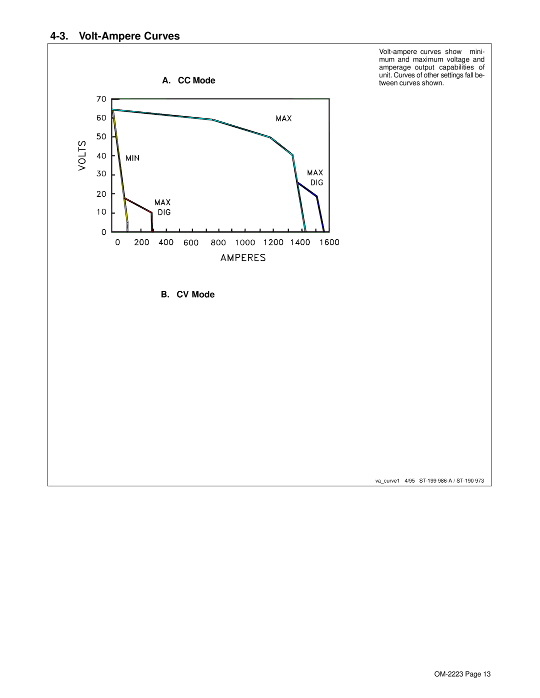
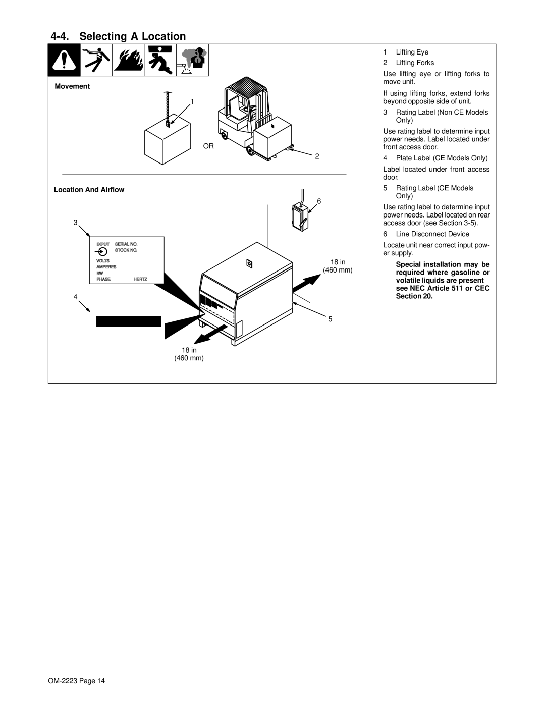
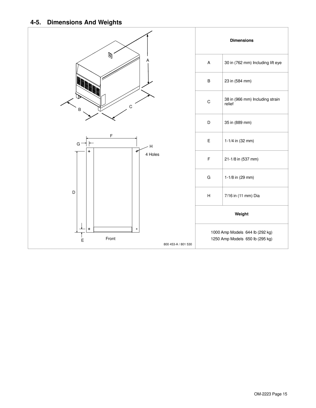
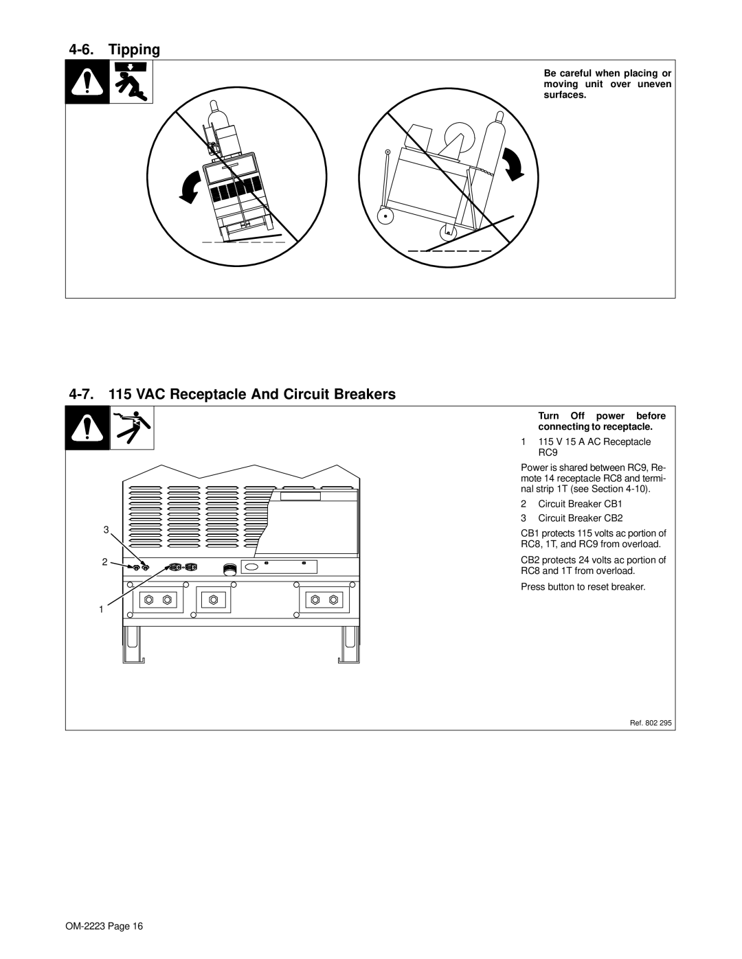
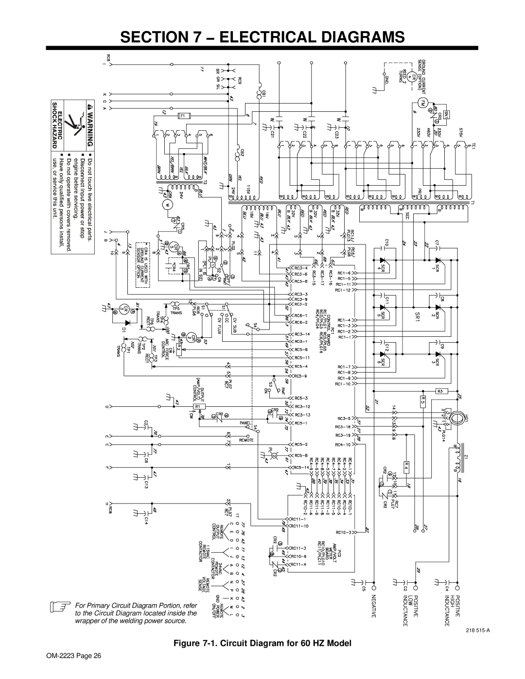
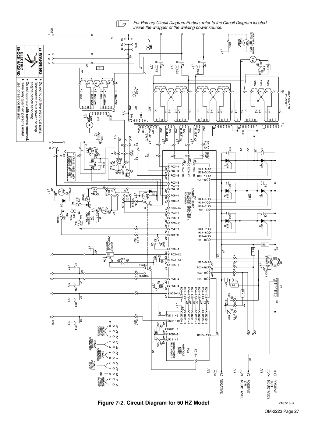
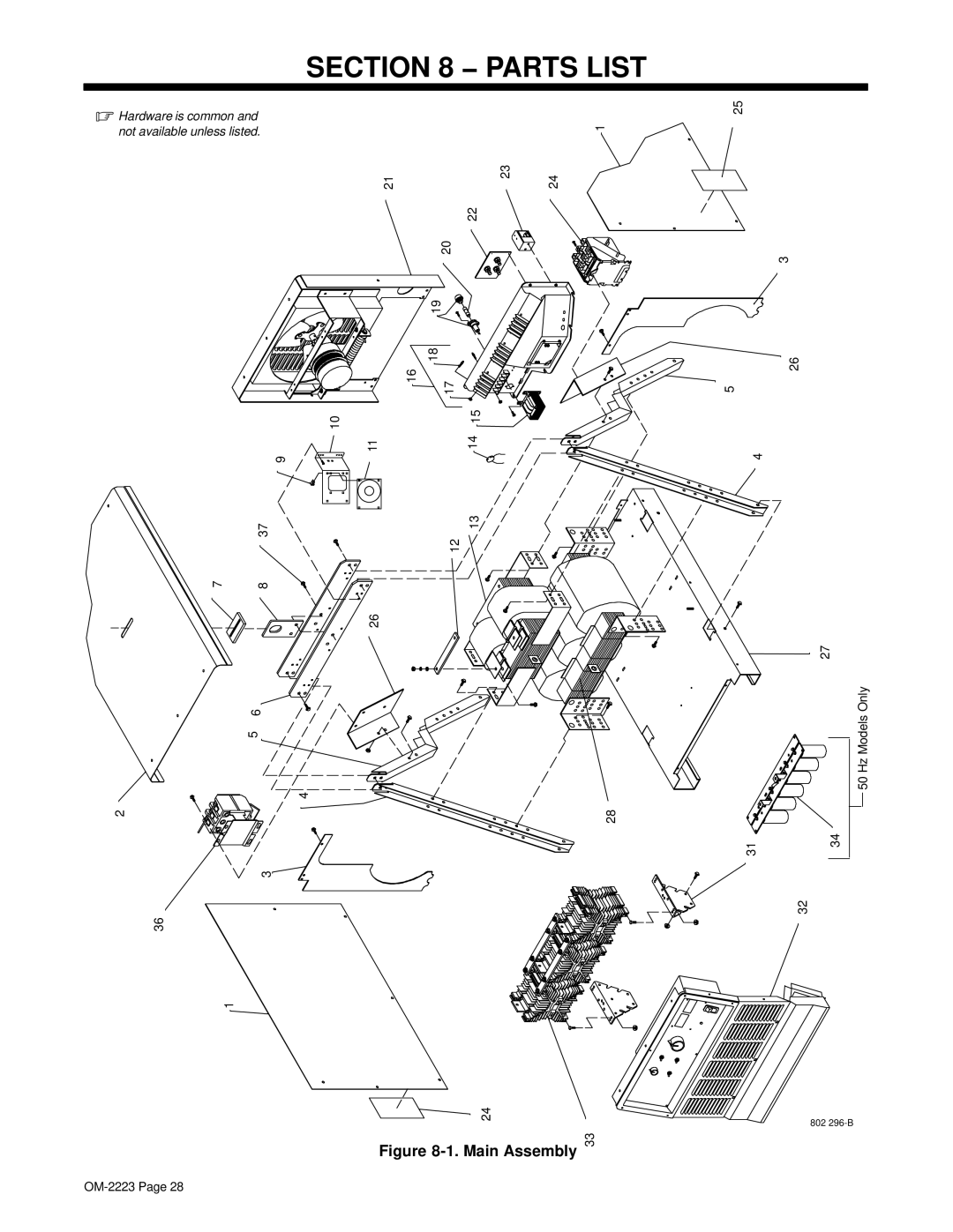
Miller Electric 1000, 1250 manual Main Assembly, PLG14

Page 33

Item

Dia.


Part


No.

Mkgs.


No.

Description

Quantity


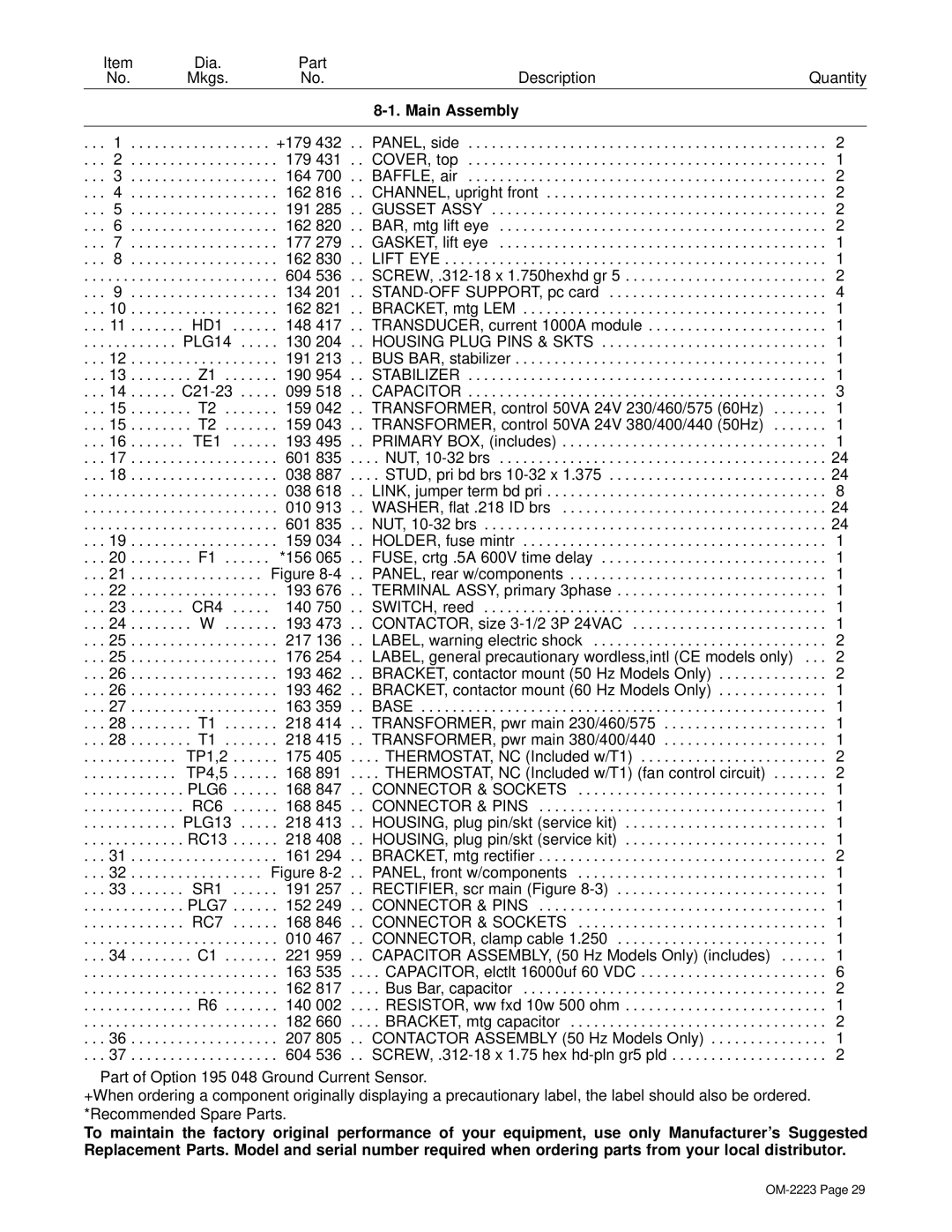
8-1. Main Assembly


. . .

1

. . . . . . .

. . . . . +179 432

. . PANEL, side

. . . 2

. . .

2

. . . . . . .

. . . . . .

179 431

. . COVER, top

. . . 1

. . .

3

. . . . . . .

. . . . . .

164 700

. . BAFFLE, air

. . . 2

. . .

4

. . . . . . .

. . . . . .

162 816

. . CHANNEL, upright front

. . . 2

. . . 5

. . . . . . .

. . . . . .

191 285

. . GUSSET ASSY

. . . 2

. . .

6

. . . . . . .

. . . . . .

162 820

. . BAR, mtg lift eye

. . . 2

. . .

7

. . . . . . .

. . . . . .

177 279

. . GASKET, lift eye

. . . 1

. . .

8

. . . . . . .

. . . . . .

162 830

. . LIFT EYE

. . . 1

. . .

. . . . . . . . .

. . . . . . .

. . . . . .

604 536

. . SCREW, .312-18 x 1.750hexhd gr 5

. . . 2

. . .

9

. . . . . . .

. . . . . .

134 201

. . STAND-OFF SUPPORT, pc card

. . . 4

. . . 10

. . . . . . .

. . . . . .

162 821

. . BRACKET, mtg LEM

. . . 1

. . . 11

. HD1

. . . . . .

148 417

. . TRANSDUCER, current 1000A module

. . . 1

. . .

. . . . . . . . .

PLG14

. . . . . 130 204

. . HOUSING PLUG PINS & SKTS

. . . 1

. . . 12

. . . . . . .

. . . . . .

191 213

. . BUS BAR, stabilizer

. . . 1

. . . 13

. . Z1 .

. . . . . .

190 954

. . STABILIZER

. . . 1

. . . 14

C21-23

099 518

. . CAPACITOR

. . . 3

. . . 15

. . T2 .

. . . . . .

159 042

. . TRANSFORMER, control 50VA 24V 230/460/575 (60Hz) . . . .

. . . 1

. . . 15

. . T2 .

. . . . . .

159 043

. . TRANSFORMER, control 50VA 24V 380/400/440 (50Hz) . . . .

. . . 1

. . . 16

. TE1

. . . . . .

193 495

. . PRIMARY BOX, (includes)

. . . 1

. . . 17

. . . . . . .

. . . . . .

601 835

. . . . NUT, 10-32 brs

. . . 24

. . . 18

. . . . . . .

. . . . . .

038 887

. . . . STUD, pri bd brs 10-32 x 1.375

. . . 24

. . .

. . . . . . . . .

. . . . . . .

. . . . . .

038 618

. . LINK, jumper term bd pri

. . . 8

. . .

. . . . . . . . .

. . . . . . .

. . . . . .

010 913

. . WASHER, flat .218 ID brs

. . . 24

. . .

. . . . . . . . .

. . . . . . .

. . . . . .

601 835

. . NUT, 10-32 brs

. . . 24

. . . 19

. . . . . . .

. . . . . .

159 034

. . HOLDER, fuse mintr

. . . 1

. . . 20

. . F1 .

. . . . .

*156 065

. . FUSE, crtg .5A 600V time delay

. . . 1

. . . 21

. . . . . . .

. . . . Figure 8-4

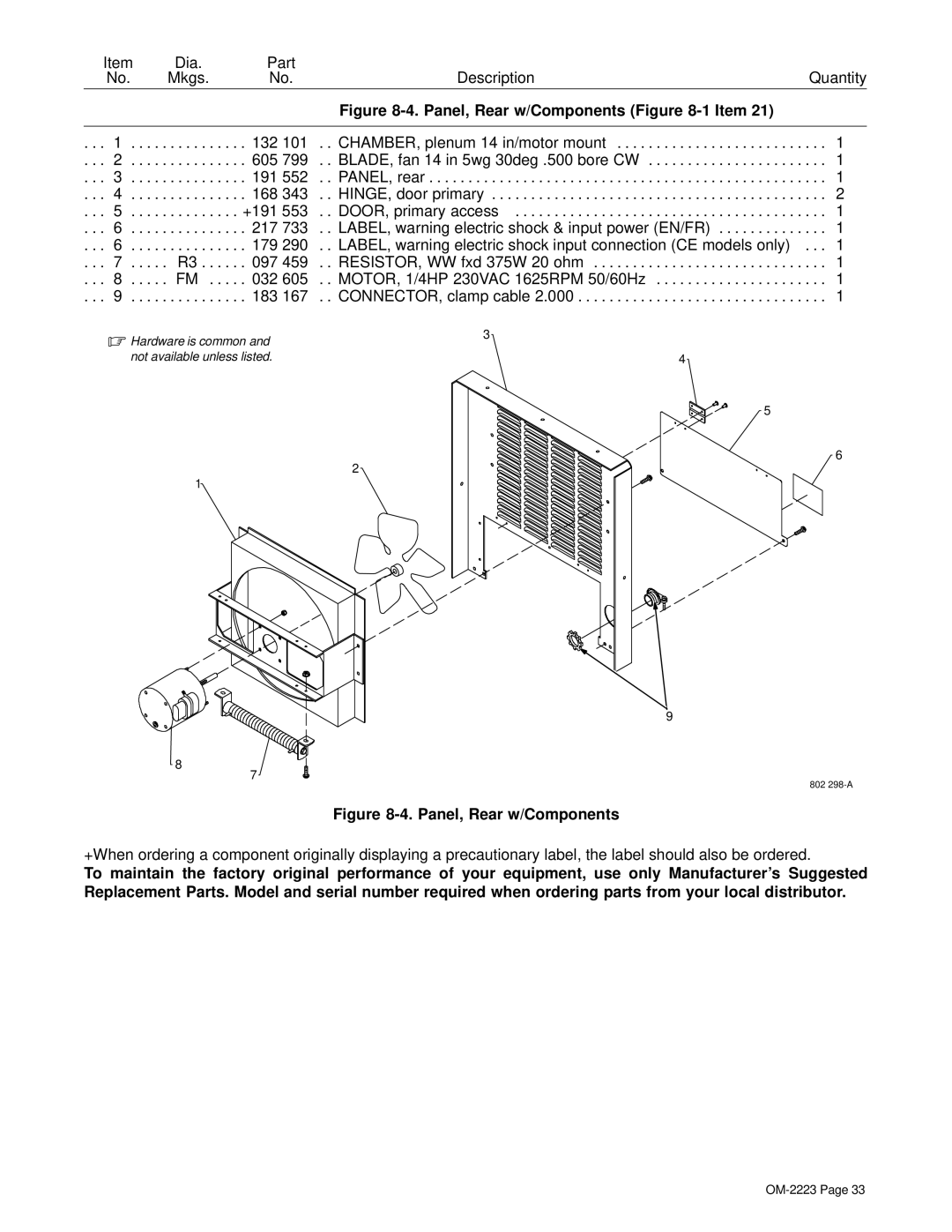
. . PANEL, rear w/components

. . . 1

. . . 22

. . . . . . .

. . . . . .

193 676

. . TERMINAL ASSY, primary 3phase

. . . 1

. . . 23

. CR4

. . . . . 140 750

. . SWITCH, reed

. . . 1

. . . 24

. . W .

. . . . . .

193 473

. . CONTACTOR, size 3-1/2 3P 24VAC

. . . 1

. . . 25

. . . . . . .

. . . . . .

217 136

. . LABEL, warning electric shock

. . . 2

. . . 25

. . . . . . .

. . . . . .

176 254

. . LABEL, general precautionary wordless,intl (CE models only)

. . . 2

. . . 26

. . . . . . .

. . . . . .

193 462

. . BRACKET, contactor mount (50 Hz Models Only)

. . . 2

. . . 26

. . . . . . .

. . . . . .

193 462

. . BRACKET, contactor mount (60 Hz Models Only)

. . . 1

. . . 27

. . . . . . .

. . . . . .

163 359

. . BASE

. . . 1

. . . 28

. . T1 .

. . . . . .

218 414

. . TRANSFORMER, pwr main 230/460/575

. . . 1

. . . 28

. . T1 .

. . . . . .

218 415

. . TRANSFORMER, pwr main 380/400/440

. . . 1

. . .

. . . . . . . . .

TP1,2

. . . . . .

175 405

. . . . THERMOSTAT, NC (Included w/T1)

. . . 2

. . .

. . . . . . . . .

TP4,5

. . . . . .

168 891

. . . . THERMOSTAT, NC (Included w/T1) (fan control circuit) . . . .

. . . 2

. . .

. . . . . . . . .

. PLG6

. . . . . .

168 847

. . CONNECTOR & SOCKETS

. . . 1

. . .

. . . . . . . . .

. RC6

. . . . . .

168 845

. . CONNECTOR & PINS

. . . 1

. . .

. . . . . . . . .

PLG13

. . . . .

218 413

. . HOUSING, plug pin/skt (service kit)

. . . 1

. . .

. . . . . . . . .

. RC13

. . . . . .

218 408

. . HOUSING, plug pin/skt (service kit)

. . . 1

. . . 31

. . . . . . .

. . . . . .

161 294

. . BRACKET, mtg rectifier

. . . 2

. . . 32

. . . . . . .

. . . . Figure 8-2

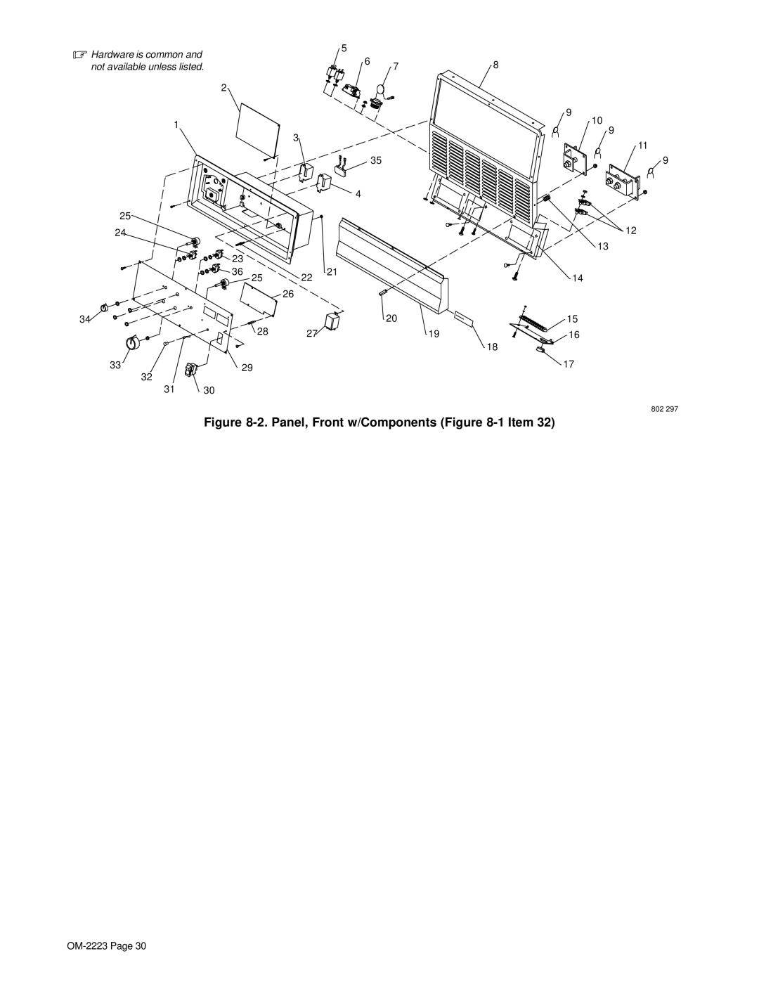
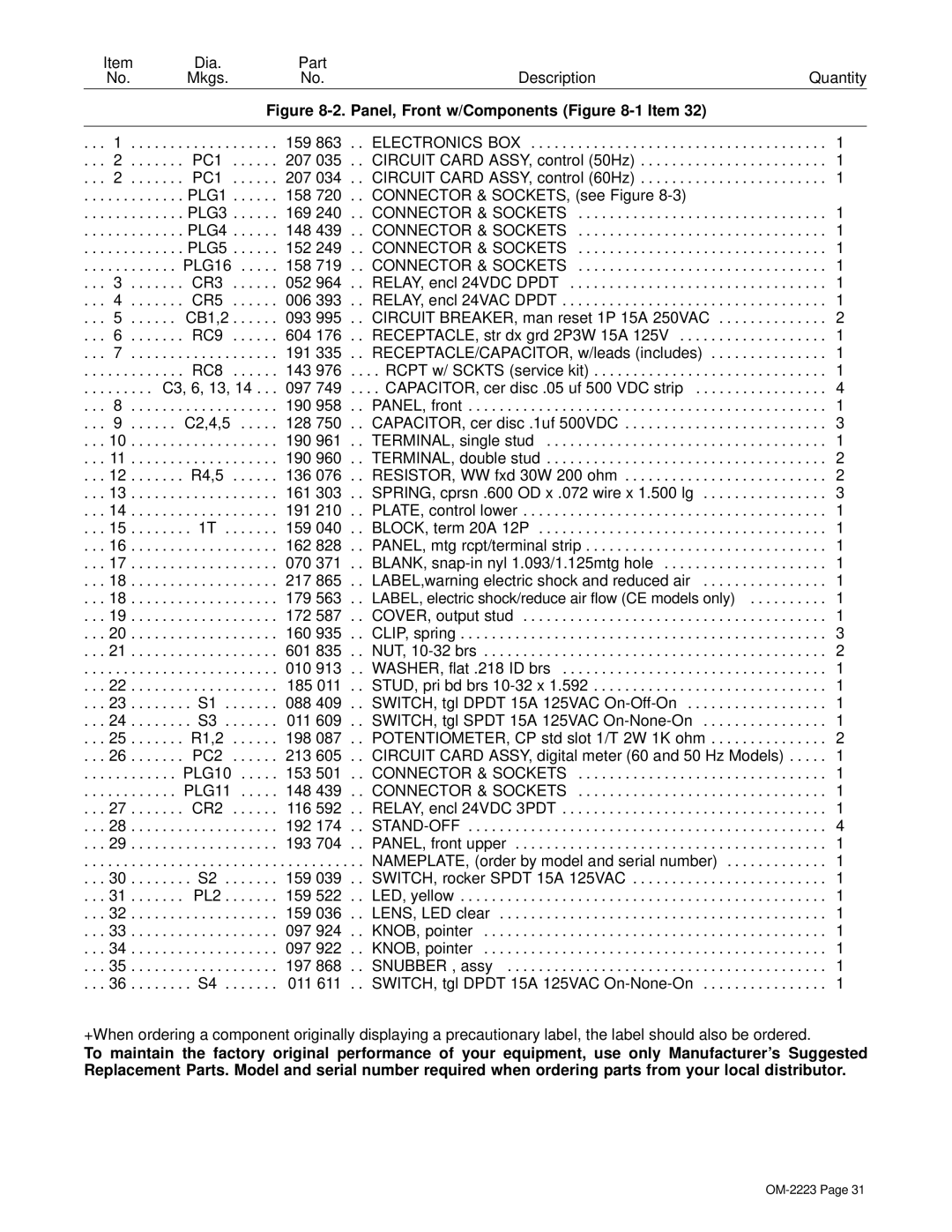
. . PANEL, front w/components

. . . 1

. . . 33

. SR1

. . . . . .

191 257

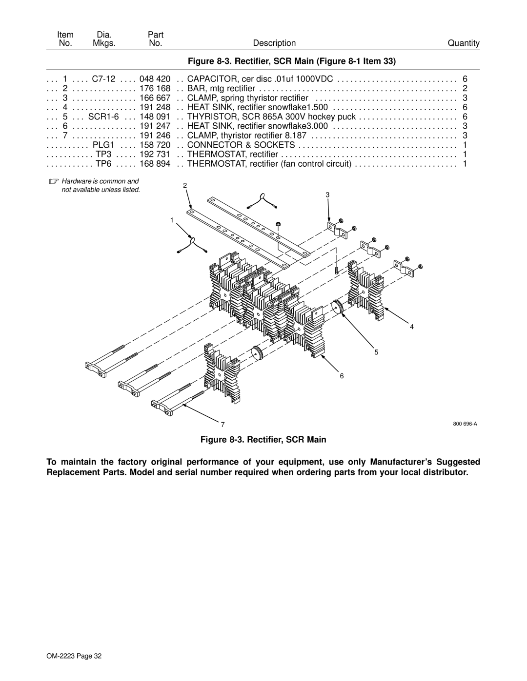
. . RECTIFIER, scr main (Figure 8-3)

. . . 1

. . .

. . . . . . . . .

. PLG7

. . . . . .

152 249

. . CONNECTOR & PINS

. . . 1

. . .

. . . . . . . . .

. RC7

. . . . . .

168 846

. . CONNECTOR & SOCKETS

. . . 1

. . .

. . . . . . . . .

. . . . . . .

. . . . . .

010 467

. . CONNECTOR, clamp cable 1.250

. . . 1

. . . 34

. . C1 .

. . . . . .

221 959

. . CAPACITOR ASSEMBLY, (50 Hz Models Only) (includes) . . .

. . . 1

. . .

. . . . . . . . .

. . . . . . .

. . . . . .

163 535

. . . . CAPACITOR, elctlt 16000uf 60 VDC

. . . 6

. . .

. . . . . . . . .

. . . . . . .

. . . . . .

162 817

. . . . Bus Bar, capacitor

. . . 2

. . .

. . . . . . . . .

. . R6 .

. . . . . .

140 002

. . . . RESISTOR, ww fxd 10w 500 ohm

. . . 1

. . .

. . . . . . . . .

. . . . . . .

. . . . . .

182 660

. . . . BRACKET, mtg capacitor

. . . 2

. . . 36

. . . . . . .

. . . . . .

207 805

. . CONTACTOR ASSEMBLY (50 Hz Models Only)

. . . 1

. . . 37

. . . . . . .

. . . . . .

604 536

. . SCREW, .312-18 x 1.75 hex hd-pln gr5 pld

. . . 2

Part of Option 195 048 Ground Current Sensor.

+When ordering a component originally displaying a precautionary label, the label should also be ordered. *Recommended Spare Parts.

To maintain the factory original performance of your equipment, use only Manufacturer’s Suggested Replacement Parts. Model and serial number required when ordering parts from your local distributor.

OM-2223 Page 29

Image 33 Contents
OM-2223 ProcessesDescription From Miller to You Table of Contents Standards DirectivesMarks a special safety message Symbol UsageArc Welding Hazards Electric Shock can killWelding can cause fire or explosion ARC Rays can burn eyes and skinFlying Metal can injure eyes Buildup of GAS can injure or killCalifornia Proposition 65 Warnings Principal Safety Standards EMF InformationAbout Pacemakers − Consignes DE Sécurité − À Lire Avant Utilisation Identifie un message de sécurité particulierLES Particules Projetées peu- vent blesser les yeux LE Soudage peut causer un incen- die ou une explosionLES Pièces Chaudes peuvent cau- ser des brûlures graves LE Bruit peut affecter l’ouïeLA Chute DE L’APPAREIL peut blesser Risque D’INCENDIE OU D’EXPLO’EMPLOI Excessif peut Faire LES Pièces Mobiles peuvent cau- ser des blessuresPrincipales normes de sécurité Information sur les champs électromagnétiquesConsignes relatives aux stimulateurs cardiaques − Definitions General Precautionary LabelInput Connection Label Nameplate Safety SymbolsElectric Shock And Airflow Label ? aManufacturer’s Rating Label For CE Products Symbol DefinitionsI1max I1eff− Installation SpecificationsDuty Cycle And Overheating Volt-Ampere Curves CC Mode CV ModeMovement Location And Airflow Selecting a LocationDimensions And Weights DimensionsWeight Turn Off power before connecting to receptacle Be careful when placing or moving unit over uneven surfacesTipping VAC Receptacle And Circuit BreakersRemote 14 Receptacle And Terminal Strip 1T Information Weld Output Terminals And Selecting Cable SizesConnecting Remote Control Electrical Service GuideAmpere Rated Welding Output 50 Hz Input Voltage Placing Jumper LinksConnecting Input Power Welding Power Source Input Power ConnectionsDisconnect Device Input Power Con- nections Work like a Pro Dimension 1000 Nameplate Dimension 1250 Nameplate − OperationControls Amperage/Voltage Adjustment Control Routine Maintenance − Maintenance & TroubleshootingDisconnect power before maintaining Fuse F1 Trouble Remedy TroubleshootingCircuit Diagram for 60 HZ Model − Electrical DiagramsCircuit Diagram for 50 HZ Model Hz Models Only PLG14 Main AssemblyPanel, Front w/Components -1Item PC1 207 Rectifier, SCR Main -1Item Panel, Rear w/Components -1Item Page Support ServiceMiller Electric Mfg. Co Owner’s Record