VIDEO | SCU |
|
|
|
| ||
OUTPUTS |
|
|
|
| |||
|
| LOCAL |
|
|
|
| |
|
| T+ T- | R- R+ |
|
|
|
|
|
|
|
|
| 3 |
| EACH KBD300V |
|
|
|
|
|
|
| |
|
|
|
|
|
|
| REQUIRES A VIDEO |
TO SCU OR PREVIOUS RX+ |
|
|
|
| R+ | CONNECTION TO A | |
KBD300V INTERFACE | RX- |
|
|
|
| R- | MONITOR OUTPUT |
OR TO WALL BLOCKS | GND |
|
|
|
|
| ON THE SCU. |
TX- |
|
|
|
| T- | 6 | |
KEYBOARDS) | TX+ |
|
|
|
| T+ | |
|
|
| 2 | RX+ |
| R+ |
|
|
|
| RX- |
| R- |
| |
TO ADDITIONAL KBD300V GND |
|
|
| ||||
INTERFACES OR TO WALL TX- |
| T- |
| ||||
BLOCKS | TX+ |
| T+ |
| |||
KEYBOARDS) |
|
|
|
|
| POWER SUPPLY | |
|
|
|
|
| 1 | KBD300V |
|
|
|
|
|
| INTERFACE |
| |
|
|
|
|
|
|
| |
5
47
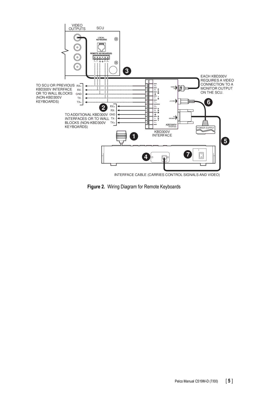
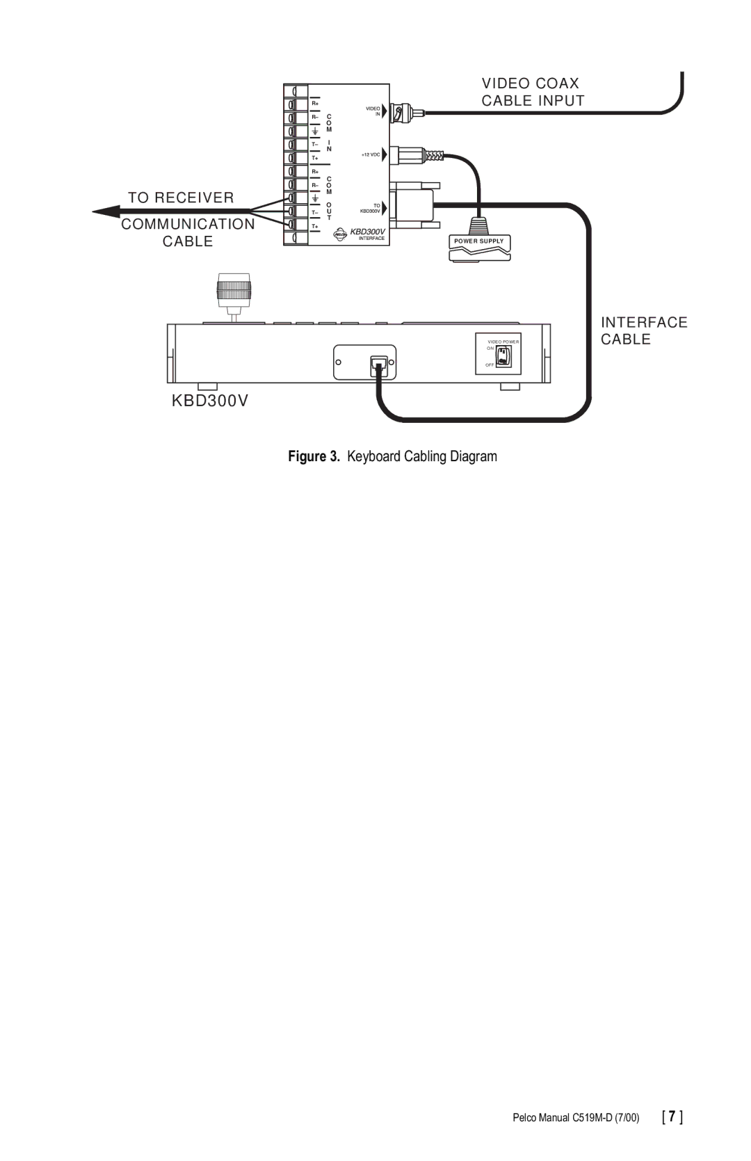
INTERFACE CABLE (CARRIES CONTROL SIGNALS AND VIDEO)
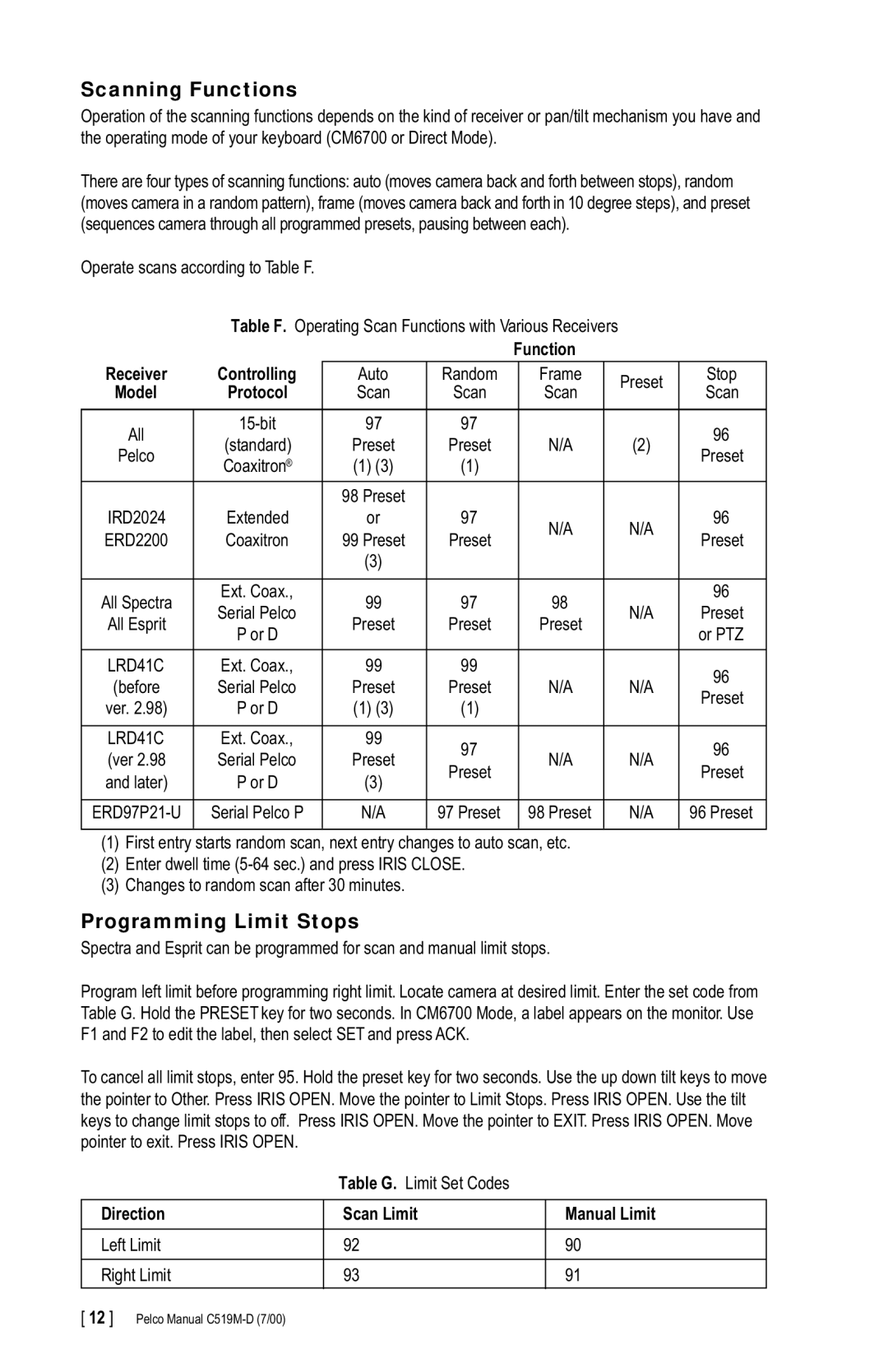
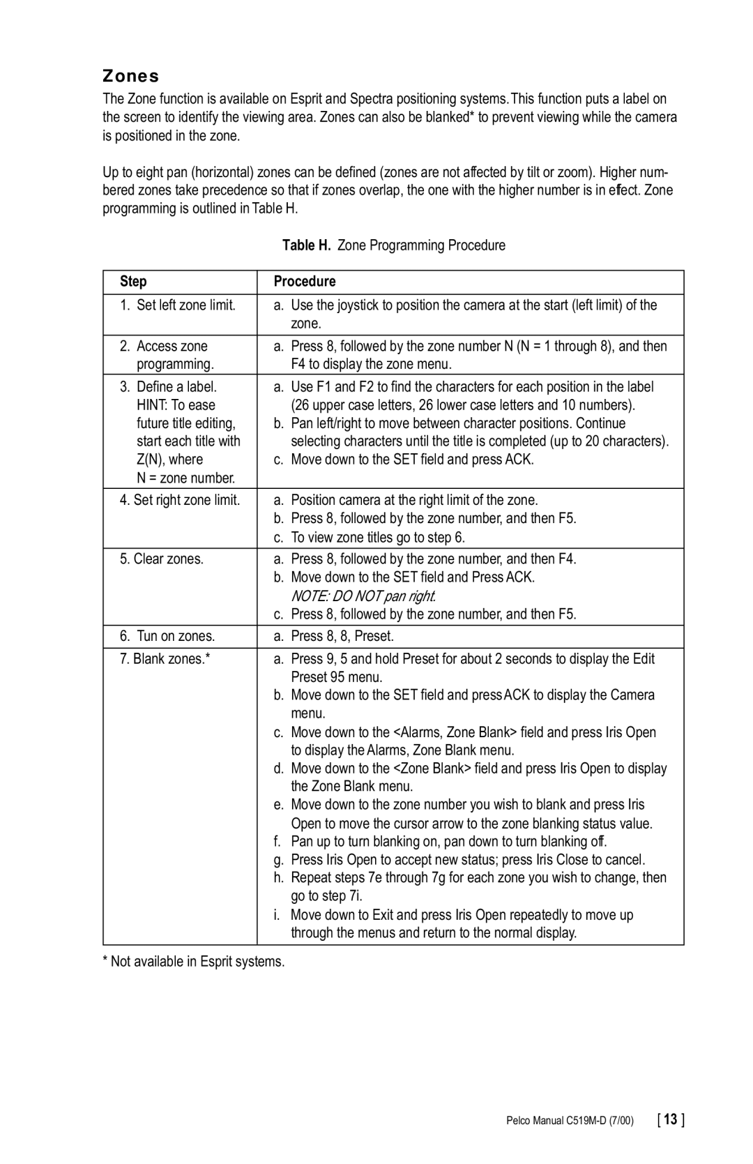
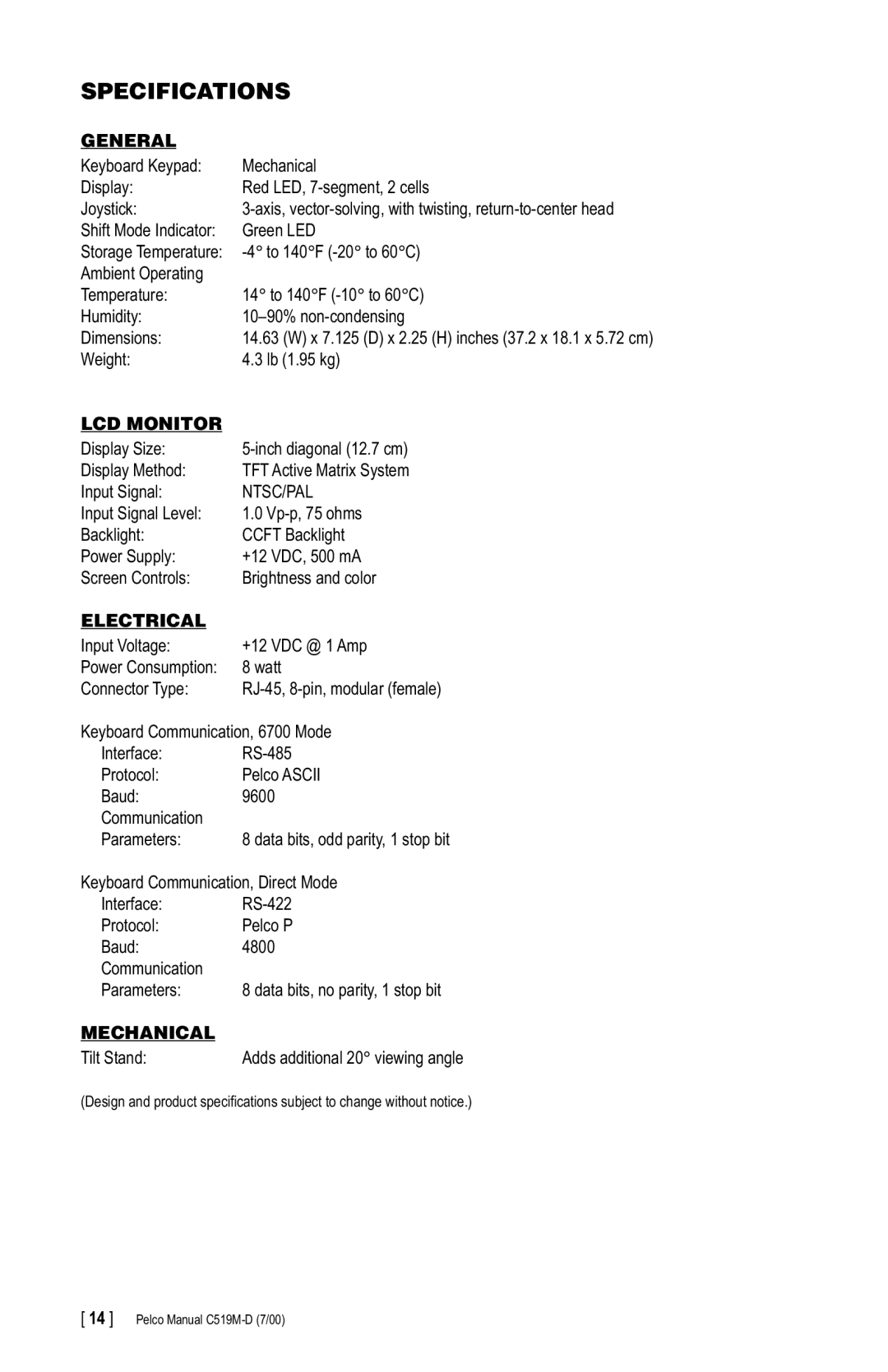
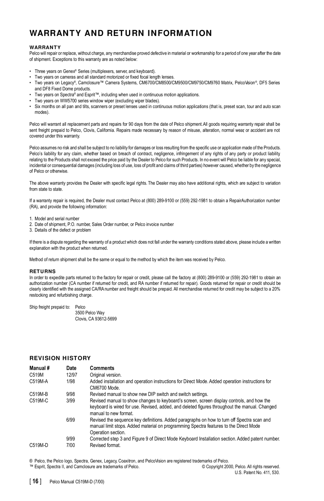
Figure 2. Wiring Diagram for Remote Keyboards
Pelco Manual | [ 5 ] |
