

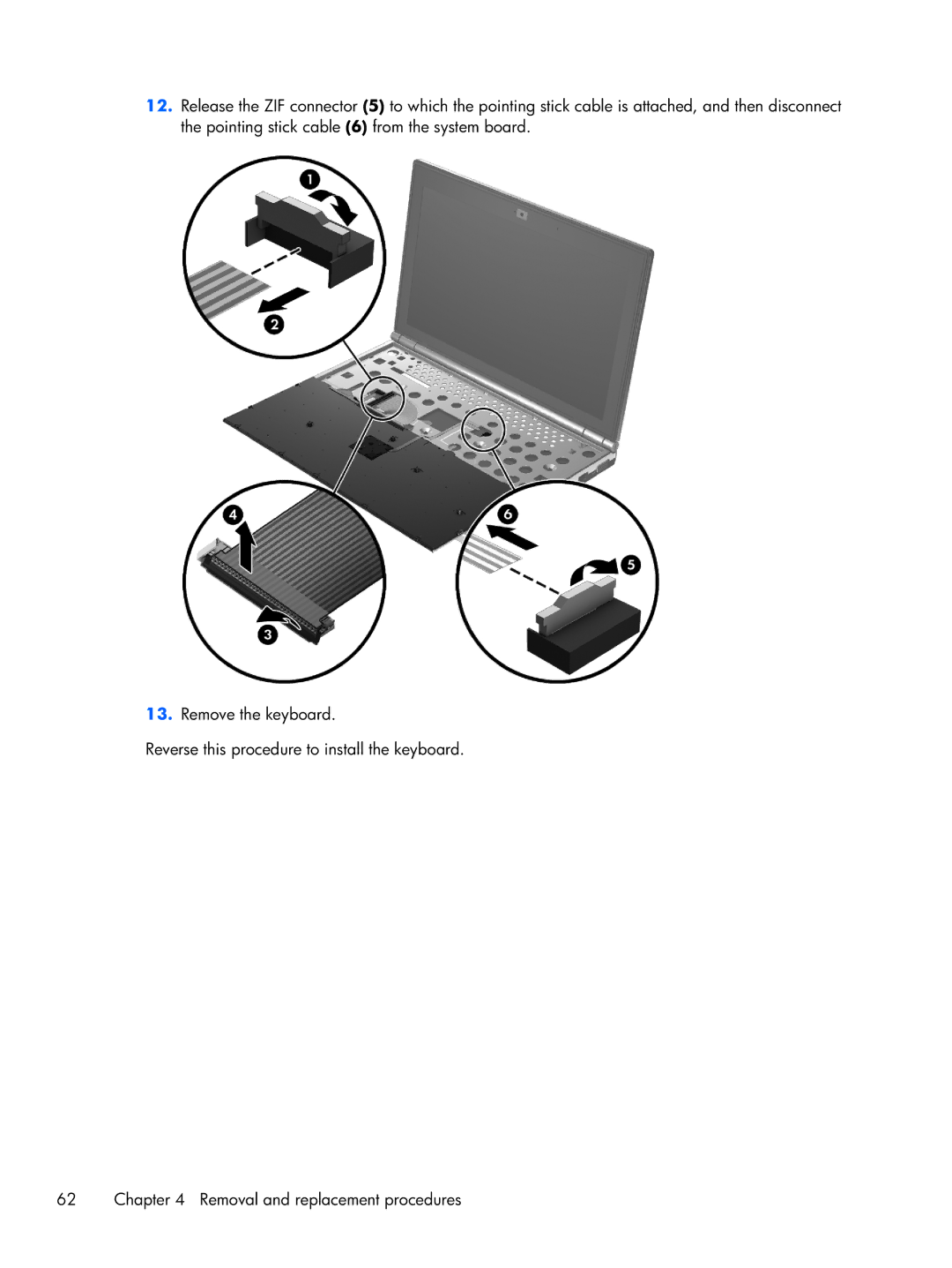

2170p B8V03UTABA specifications
The HP 2170p B8V03UTABA is a notable addition to HP's lineup of business laptops, designed for professionals who require portability without sacrificing performance. This model stands out for its exceptional balance of durability, features, and ergonomic design, making it an ideal choice for mobile professionals.The HP 2170p boasts a sleek and compact form factor, weighing in at just over three pounds. Its lightweight design makes it easy to carry, fitting comfortably into most briefcases or bags. The laptop features a 11.6-inch display, which provides a crisp and clear viewing experience, perfect for presentations and working on documents. The display’s resolution typically reaches 1366 x 768 pixels, which ensures that visuals are detailed and text is easy to read.
Under the hood, the HP 2170p is powered by Intel's processors, allowing users to choose from various configurations based on their performance needs. The integration of Intel's technology ensures efficient energy consumption, extending battery life, which is crucial for business users who are often on the move. The laptop typically features 4GB or more of RAM, ensuring smooth multitasking capabilities when handling multiple applications or browser tabs.
One of the key highlights of the HP 2170p is its robust security features. With options for a fingerprint reader and HP's BIOS protection, users can rest assured that their data is secure from unauthorized access. This focus on security makes it a suitable option for corporate environments that prioritize data protection.
Durability is another strong suit of the HP 2170p. It is built to withstand the rigors of daily travel, with a spill-resistant keyboard and a reinforced chassis. These features help protect the device against accidental drops and spills, making it a reliable companion for busy professionals.
Connectivity options are plentiful on this model. It offers USB 3.0 and USB 2.0 ports, HDMI output, and an SD card reader, ensuring compatibility with a wide range of peripherals and accessories. Furthermore, it supports Wi-Fi and Bluetooth technologies, allowing for seamless connectivity on the go.
Overall, the HP 2170p B8V03UTABA is an excellent choice for users seeking a compact yet powerful laptop that excels in both functionality and security. Its combination of portability, durability, and performance makes it a valuable asset for professionals looking to enhance their productivity while on the move.