HP Pro 4300 manual

Page 64

3.Rotate up the drive bay housing to access the memory module sockets on the system board. Figure 7-6Rotating the Drive Cage Up

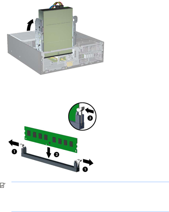
4.Open both latches of the memory module socket (1), and insert the memory module into the socket (2).

Figure 7-7Installing a DIMM

NOTE: A memory module can be installed in only one way. Match the notch on the module with the tab on the memory socket.

A DIMM must occupy the black XMM1 socket.

For maximum performance, populate the sockets so that the memory capacity is equal between Channel A and Channel B. Refer to Populating DIMM Sockets on page 55 for more information.

5.Push the module down into the socket, ensuring that the module is fully inserted and properly seated. Make sure the latches are in the closed position (3).

56 Chapter 7 Removal and Replacement Procedures Small Form Factor (SFF) Chassis

Image 64
Contents Maintenance and Service Guide HP Compaq Pro 4300 Small Form Factor Business PC About This Book Table of contents Smart ATA Drives 101 107 163 Product Features Standard Configuration FeaturesFront Panel Components 1Front Panel ComponentsRear Panel Components 2Rear Panel Components4Serial Number and Product ID Location Product Features Serial Number LocationActivating and customizing the software in Windows Activating and Customizing the SoftwareActivating the Windows operating system Installing or upgrading device drivers Downloading Windows 7 updatesCustomizing the monitor display Downloading Windows 8 updates Click Settings Change PC SettingsComputer Setup F10 Utility Computer Setup F10 UtilitiesUsing Computer Setup F10 Utilities 1Computer Setup F10 UtilityComputer Setup-File 2Computer Setup-FileComputer Setup-Storage 3Computer Setup-StorageSata Defaults OptionDescriptionRemovable Media Boot Storage Options ESATA PortSata Emulation Max eSATA SpeedShortcut to Temporarily Override Boot Order Boot OrderDPS Self-Test Computer Setup-Security 4Computer Setup-SecurityNetwork Boot Master Boot RecordSlot Security System IDsSystem Security Configuration Secure BootDriveLock Security Computer Setup-Power 5Computer Setup-Power6Computer Setup-Advanced for advanced users Computer Setup-AdvancedOption Heading Power-On Options Bios Power-On Onboard DevicesBus Options Device OptionsVGA Configuration Recovering the Configuration SettingsAMT Configuration Serial ATA Sata Drive Guidelines and Features Serial ATA Hard Drive CharacteristicsSata Hard Drives Sata Hard Drive CablesSmart ATA Drives Chassis Designations Small Form Factor SFFElectrostatic Discharge Information Generating StaticPreventing Electrostatic Damage to Equipment Relative Humidity Event 55% 40% 10%Personal Grounding Methods and Equipment Grounding the Work AreaRecommended Materials and Equipment Static Shielding Protection LevelsOperating Guidelines General Cleaning Safety Precautions Cleaning the Computer CaseCleaning the Keyboard Routine CareService Considerations Cleaning the MonitorCleaning the Mouse Power Supply FanCables and Connectors Tools and Software RequirementsScrews Hard DrivesLithium Coin Cell Battery Spare parts Illustrated parts catalogComputer major components Description Spare part number Access panel Power supplyHeat sink includes replacement thermal material Front I/O and power switch assemblyDescription Spare part number Optical drivesExpansion cards KeyboardMouse Sequential part number listing Spare parts Illustrated parts catalog Spare parts Illustrated parts catalog Spare parts Illustrated parts catalog Spare parts Illustrated parts catalog Spare parts Illustrated parts catalog Spare parts Preparation for Disassembly 1Serial Number and Product ID LocationPage Computer Access Panel Description Spare part number Access panel 636924-001Front Bezel Description Spare part number Front bezel 695080-001Bezel Blanks System Board Connections System Board Connector System Board Label Color Component 1System Board Connections DIMMs Installing Additional MemoryDDR3-SDRAM DIMMs Installing DIMMs Populating Dimm SocketsPage Graphics cards for models with Windows Removing or Installing an Expansion CardOther boards Remove the access panel Computer Access Panel on Page Page Page Page Page Cable Management Description Spare part number Optical drives DrivesDrive cables Drive Positions Installing and Removing Drives2Drive Positions 3Extra Mounting Screws Mounting Screw DeviceRemoving an Internal 5.25-inch Drive Rotate the drive cage back down to its normal position Installing an Optical Drive into the 5.25-inch Drive Bay 24Connecting the Power and Data Cables Drives Removing an Internal 3.5-inch Drive Page Installing a Drive into the 3.5-inch Internal Drive Bay 33Rotating the Drive Cage Down Drives Page 36Raising the Power Supply Drives Page Page Baffle Description Spare part number Baffle 636921-001Front Fan Assembly Description Spare part number Front fan assembly 636922-001Front I/O, Power Switch Assembly Remove the chassis fan Front Fan Assembly onSpeaker Description Spare part number Speaker 636925-001Heat sink Description Spare part number Heat sink 636919-00147Removing the heat sink screws Heat sink Page Processor Page Power Supply Pwrcmd4Power supply cable system board connector Power supply connector label System board connectorSystem Board Page Battery Type 1 Battery Holder Type 2 Battery HolderType 3 Battery Holder Using the Small Form Factor Computer in a Tower Orientation Installing a Security Lock HP/Kensington MicroSaver Security Cable LockPadlock Front Bezel Security Page Japanese Power Cord Requirements Power Cord Set RequirementsGeneral Requirements Country-Specific Requirements Country Accrediting AgencyPost Error Messages Post Numeric Codes and Text Messages Table B-1Numeric Codes and Text MessagesControl panel message Description Recommended action Test under Storage DPS Self-testTable B-2Diagnostic Front Panel LEDs and Audible Codes Activity Blinks Possible CauseActivity Blinks Possible Cause Recommended Action Troubleshooting Without Diagnostics Safety and Comfort Before You Call for Technical SupportHelpful Hints Refer to Helpful Hints on page 108 in this guidePage Solving General Problems Table C-1Solving General ProblemsComputer date and time display is incorrect Cause Solution Computer will not respond to keyboard or mouse CauseThere is no sound or sound volume is too low Cause Solution Cannot remove computer cover or access panel CausePoor performance Cause Solution Advanced Device OptionsAll apps icon Under Windows System, click RunCause Solution Table C-2Solving Power Problems Solving Power ProblemsPower supply shuts down intermittently Cause Solution Some models, is set to the appropriate voltage. Proper Solving Hard Drive Problems Table C-3Solving Hard Drive ProblemsNonsystem disk/NTLDR missing message Cause Solution Computer will not boot from hard drive Cause SolutionStorage Boot Order Device ConfigurationComputer seems to be locked up Cause Solution Table C-4Solving Media Card Reader Problems Solving Media Card Reader ProblemsCan not write to the media card Cause Computer’s software is used to safely eject the card Solving Display Problems Table C-5Solving Display ProblemsBlank screen no video Cause Solution Adjust screen resolutionDim characters Cause Solution No Connection, Check Signal Cable displays on screen Cause Image is not centered Cause SolutionSelect ImageControl/ Horizontal Position or Vertical Out of Range displays on screen Cause Certain typed symbols do not appear correct Cause Solving Audio Problems Table C-6Solving Audio ProblemsThere is no sound or sound volume is too low Cause Sound from headphones is not clear or muffled CauseLine-in jack is not functioning properly Cause Solving Printer Problems Table C-7Solving Printer ProblemsPrinter will not print Cause Solution Printer will not turn on Cause SolutionPrinter prints garbled information Cause Solution Solving Keyboard and Mouse Problems Table C-8Solving Keyboard ProblemsTable C-9Solving Mouse Problems EnterSolving Hardware Installation Problems Table C-10Solving Hardware Installation ProblemsControl Panel , and then select Device Manager Security USB SecurityComputer will not start Cause Solution Solving Network Problems Table C-11Solving Network ProblemsNetwork status link light never flashes Cause Solution ManagerDiagnostics reports a failure Cause Solving Memory Problems Table C-12Solving Memory Problems Out of memory error Cause SolutionMemory count during Post is wrong Cause Solution Insufficient memory error during operation Cause SolutionSolving Processor Problems Solving CD-ROM and DVD ProblemsTable C-13Solving Processor Problems Table C-14Solving CD-ROM and DVD ProblemsSecurity Network Boot Movie will not play in the DVD drive Cause SolutionSolving USB Flash Drive Problems Cannot eject compact disc tray-load unit CauseUSB flash drive not found identified Cause Solution Table C-15Solving USB Flash Drive ProblemsSystem will not boot from USB flash drive Cause Solution Solving Front Panel Component Problems Solving Internet Access ProblemsPorts are set to Enabled in Security USB Security Unable to connect to the Internet Cause SolutionSelect Start Control Panel Click Internet OptionsSolving Software Problems Appendix C Troubleshooting Without Diagnostics Contacting Customer Support HP PC Hardware Diagnostics Why run HP PC Hardware DiagnosticsHow to access and run HP PC Hardware Diagnostics Downloading HP PC Hardware Diagnostics to a USB device Backup and Recovery Restoring and recovering in WindowsSystem Restore System RecoverySystem Recovery when Windows is responding System Recovery when Windows is not responding Creating recovery media Using recovery media Backup and recovery in Windows Backing up your informationPerforming a system recovery Using the Windows recovery toolsUsing f11 recovery tools Password Security and Resetting CmosResetting the Password Jumper Clearing and Resetting the Cmos Figure F-1 Cmos buttonPage Drive Protection System DPS Accessing DPS Through Computer Setup Select Storage DPS Self-TestSpecifications Table H-1SpecificationsAppendix H Specifications Index CmosDVI-D Sata
Related manuals
Manual 2 pages 47.5 Kb Manual 162 pages 51.63 Kb Manual 3 pages 56.05 Kb