Carvin CX1252 manual Speaker Connections, Tape Decks and External Effects, Channel PAN Control

Page 4

SPEAKER CONNECTIONS

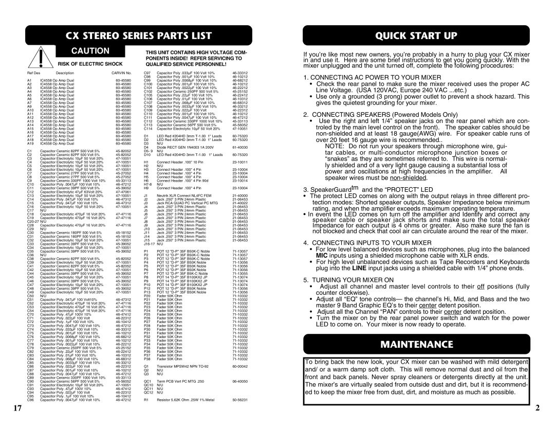
Here are two possible speaker connections, two or four 8 ohm speakers with one or one pair to each 1/4” speaker output. Also two 4 ohm speakers can be connected one to each speaker output. Never go below 4 ohms on either of the two speaker output jacks, this would result in premature distortion, thermal shut down, and/or possible damage to the internal power amplifier.

SPEAKERS

SPEAKERS

RIGHT LEFT

RIGHT LEFT

4

4

4

4

MINIMUM

IMPEDANCE

MINIMUM

IMPEDANCE

250

250 WATTS


250

250 WATTS


MADE IN THE


MADE IN THE


USA


USA


8 OHM MINIMUM

8 OHM MINIMUM

4 OHM MINIMUM

4 OHM MINIMUM

6. CHANNEL PAN CONTROL


The PAN control adjusts where the channel is heard in


the stereo field of the stereo main outputs. If it is turned


to the extreme left, then the channel will only be heard in

10

the left main output and similarly only in the right main


output if turned to the extreme right. In the center posi-


tion the channel is heard equally in both the left and right

9

main outputs. A good starting point for the pan is in the

center position. Then if stereo placement is needed, a


quarter turn to the desired side from the center position


gives a smooth placement in the stereo field, or if desired

8

a full turn to one side gives a hard placement.

7.CHANNEL EFFECTS/REVERB LEVEL CONTROL

The EFF/REV control adjusts the volume of the channel

going to the effects send master control, and/or the inter- 7 nal DSP effects (if DSP is present). The effects control is post channel level. This means adjustments in the chan- nel’s EQ or level controls will be affecting the effects mix

output of that channel.

6

8-10. CHANNEL TONE CONTROLS

1

HI 3 0 3

6

6

99

12 12

MID

0


3

3


6


6


99

12 12

LOW

0

3

3


6


6


99

12 12

EFF /

REV 4 5 6

3 7

28

19

0 10

PAN 0

L

R

8 OHM MINIMUM

8 OHM MINIMUM

TAPE DECKS AND EXTERNAL EFFECTS

Each channel features three tone controls LO, MID, and HI. The LO and HI con- trols are shelving type tone controls with corner frequencies at 100Hz and 10KHz respectively. The shelving means, the for the LO control, all frequencies from 100Hz down to the lowest frequency the mixer can handle are all boosted when the knob is turned clockwise and cut when turned counter-clockwise from the center position. For the HI control the shelving means all the frequencies from 10kHz and up to the upper limit of the mixer are all boosted when the knob is turned clockwise and cut when turned counter-clockwise from the center posi- tion. The MID control is a band pass type of tone control. The band pass

L/R MAIN


CX1252


4

5

6


STEREO DSP


3


7


2


8


1


9

PHANTOM

POWER


BYPASS 1


0


10


DELAYS 2-30


4

5

6

4

5

6


127 EFFECTS

REVERB

31-90


CHORUS

91-110


3


7

3


7


FLANGE 111-128


2


8

2


8


1


9

1


9


L

R


0


10

0


10


MONITOR

DSP EFF RTN


TAPE


L

R


4

5

6

4

5

6


SEND


3


7

3


7


2


8

2


8


1


9

1


9


TAPE


AMP


0


10

0


10


RTN


EFF SEND

TAPE / EFF RTN


L

R

PATCH


SEND

L RETURN R


L

R


AMP


PROTECT


EFFECTS


MONITOR

LINE OUT


TWO-TRACK

TAPE OUT

TAPE IN


TAPE RECORDER

MONO IN

L OUT R

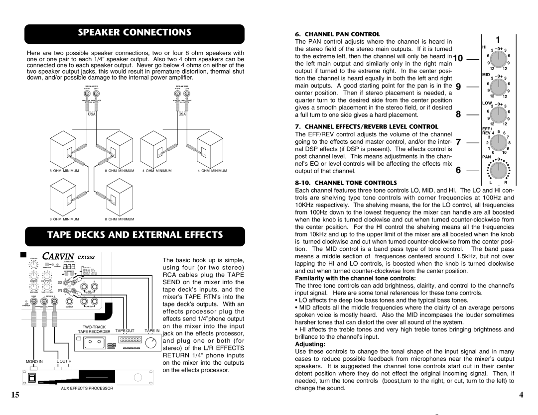
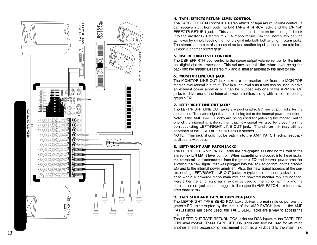
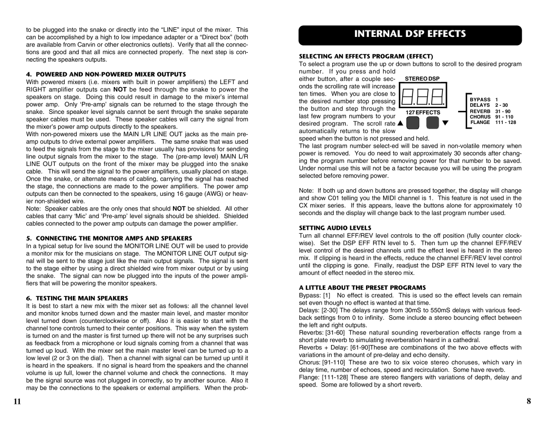
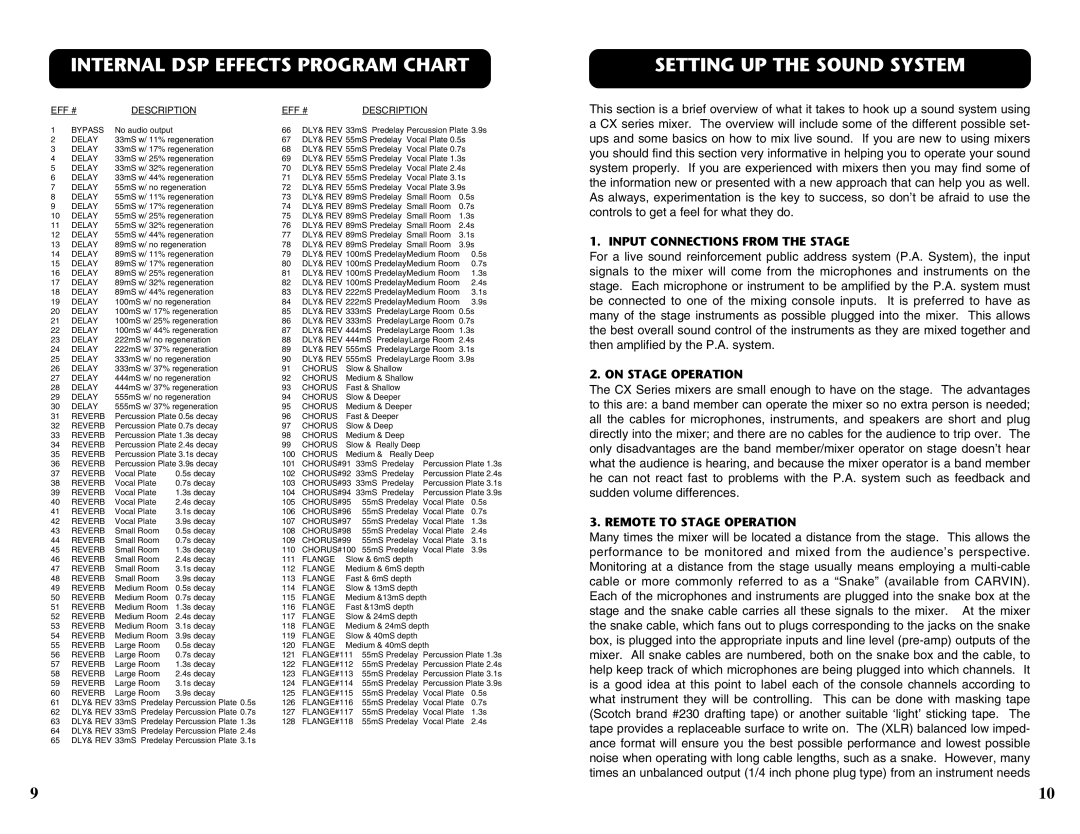
The basic hook up is simple, using four (or two stereo) RCA cables plug the TAPE SEND on the mixer into the tape deck’s inputs, and the mixer’s TAPE RTN’s into the tape deck’s outputs. With an effects processor plug the effects send 1/4”phone output on the mixer into the input jack on the effects processor, and plug one or both (for stereo) of the L/R EFFECTS RETURN 1/4” phone inputs on the mixer into the outputs on the effects processor.

means a middle section of frequences centered around 1.5kHz, but not over lapping the HI and LO controls, is boosted when the knob is turned clockwise and cut when turned counter-clockwise from the center position.

Familarity with the channel tone controls:

The three tone controls can add brightness, clairity, and control to the channel’s input signal. Here are some tonal references for these tone controls.

• LO affects the deep low bass tones and the typical bass tones.

• MID affects all the middle frequencies where the clairty of an average persons

spoken voice is mostly heard. Also the MID incompases the louder sometimes

harsher tones that can distort the over all sound of the system.

• HI affects the treble tones and very high treble tones bringing brightness and

brillance to the channel’s input.

Adjusting:

Use these controls to change the tonal shape of the input signal and in many

cases to reduce possible feedback from microphones near the mixer’s output

speakers. It is suggested the channel tone controls start out in their center

detent position where they do not effect the original incoming signal. Then, if

needed, turn the tone controls (boost,turn to the right, or cut, turn to the left) to

AUX EFFECTS PROCESSOR

change the sound.

15

4

Image 4
Contents Helpline CX Mixer Specifications Fuse SelectionReceiving Inspection For the NEW OwnerMaintenance CX Stereo Series Parts ListQuick Start UP Speaker Connections Tape Decks and External EffectsChannel PAN Control Channel EFFECTS/REVERB Level ControlTAPE/EFFECTS Return Level Control DSP Return Level ControlMonitor Line OUT Jack LEFT/RIGHT Line OUT JacksInternal DSP Effects Warranty and Service Information Do not OpenTable of Contents Channel Features Master Section Features CX1252Power LED Phantom Power Switch and LEDTesting the Monitor Amplifier and Speakers Protect LEDInternal DSP Effects Program Chart Setting UP the Sound SystemInput Connections from the Stage On Stage Operation