MSI Z87-GD65-GAMING manual JTPM1 TPM Module Connector, JCOM1 Serial Port Connector

Page 43

JTPM1:TPM Module Connector

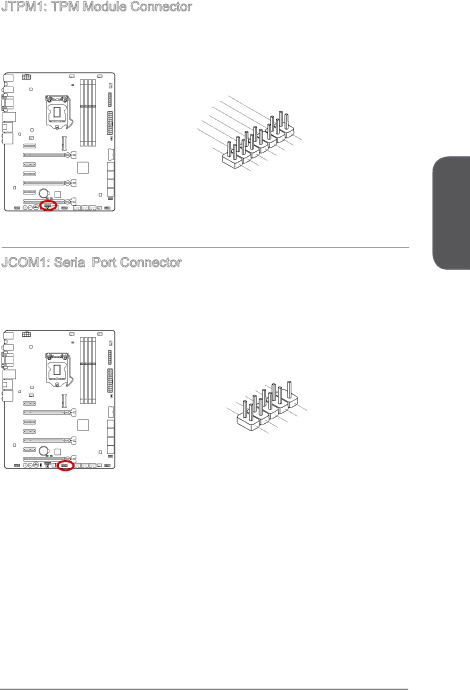
This connector connects to a TPM (Trusted Platform Module). Please refer to the TPM security platform manual for more details and usages.


14


12


.


6 .


No

Ground


10


.


4


.

5V


GroundPi

.


8 .


Serial


n


.

3V


P


ower


3


2 .


IRQ

3V


P


Standby


ower


p


ower


13


911

. LP


.


. LP LPC

C


3


7 .


a


. LP


a

Fram


5


C


LP


C


ddres


e


. LP


ddres


LP


a


1


C


.


C


ddres


C


a


s


Reseddres


s


&


loc


s


&


data


C


k


data


p


t


&

&


s


data


p


data


p in2 in3


p in1


in0


Chapter 1

JCOM1: Serial Port Connector

This connector is a 16550A high speed communication port that sends/receives 16 bytes FIFOs. You can attach a serial device.


1


0


8 .


6


. N


C


o


.


T


P

4


D


S

i


S


n

2

.


D


R


.


T


S


R


I


N


9


7

.


R


5


.


I


R


3


.


T


G


1


.


r


S


S


o


.


O


u


D


U


n


C


d


T


D


1-29

Getting Started

Image 43
Contents G52-78451X1 PrefacePreface Smartphone Application Technical Support Safety Instructions CE Conformity Korea Warning Statements Battery Information Weee Waste Electrical and Electronic Equipment Statement Español Türkçe Contents Quick Installation Appendix a Realtek Audio Page Chapter Optional Accessories Packing ContentsAssembly Precautions CPU Motherboard SpecificationsBios Nvidia SLI Connectors Quick Guide Connectors Reference Guide Back Panel Quick Guide LED Introduction to the LGA 1150 CPU CPU Central Processing UnitVideo Demonstration CPU & Heatsink InstallationChapter Chapter Memory Dual -Channel mode Population RuleMounting Screw Holes JPWR1~2 ATX Power Connectors Power SupplyPCIE1~7 PCIe Expansion Slot Expansion SlotsVideo/ Graphics Cards Single Video Card InstallationAMD CrossFire Multi -GPU Technology Chapter Nvidia SLI Technology Choose this item SATA1~6 Sata Connector Internal ConnectorsCPUFAN1~2,SYSFAN1~3 Fan Power Connectors JFP1, JFP2 System Panel Connectors JUSB1~3 USB 2.0 Expansion Connector JCI1 Chassis Intrusion Connector JUSB4 USB 3.0 Expansion ConnectorJCOM1 Serial Port Connector JTPM1 TPM Module ConnectorMSATA1 mSATA Slot JAUD1 Front Panel Audio ConnectorVoltage Checkpoints FV1 V-Check ConnectorsOC1 OC Genie Button ButtonsRESET1 Reset Button POWER1 Power ButtonFASTB1 GO2BIOS Button JBAT1 Clear Cmos Jumper JumpersMulti Bios Switch Multi -BIOS Switch SwitchOCSWITCH1 OC Genie Mode Switch Bios LEDs LED Status IndicatorsOC Switch LEDs Debug Code LED Table Drivers and Utilities Total InstallerPage Quick Installation CPU Installation Quick Installation Memory Installation Motherboard Installation Chapter Power Connectors Installation Chapter Sata HDD Installation MSATA SSD Installation JFP1 Connecotr Installation Front Panel Connector InstallationFront Panel Audio Connector Installation USB2.0 Connector Installation Peripheral Connector InstallationUSB3.0 Connector Installation Graphics Card Installation Chapter Bios Setup Entering Bios Setup Entering SetupPress DEL key to enter Setup Menu, F11 to enter Boot Menu Overview Bar Operation System Status SettingsAdvanced Enables the Ipv6 PXE boot support IGD Partition size must be larger then the amount of memory Regulation Disabled Disables MSI Fast Boot Boot settings Security BootSave & Exit This setting will be configured automatically by Bios LC PLL Profile UnLink Protection Over-current protection MEMORY-Z Can function as multiple systems virtually Then C0 Flash OC Profile Hardware Monitor Chapter Appendix a Software panel overview Software ConfigurationAuto popup dialog Hardware Default Setting Backpanel audio jacks to 6-channel speakers diagram Page Appendix B Introduction Appendix BUsing Intel Rapid Storage Technology Option ROM XXX.X GB Appendix B XXXX-XXXXXXXX Press Y key to accept the volume deletion XXXX-XXXXXXXX Recovery Volume Options Main Menu Degraded RAID ArrayAppendix B System Acceleration optional Appendix B Disk Port RST Synchronization optional