


B. Intellifire Ignition System
Symptom | Possible Cause | Corrective Action |
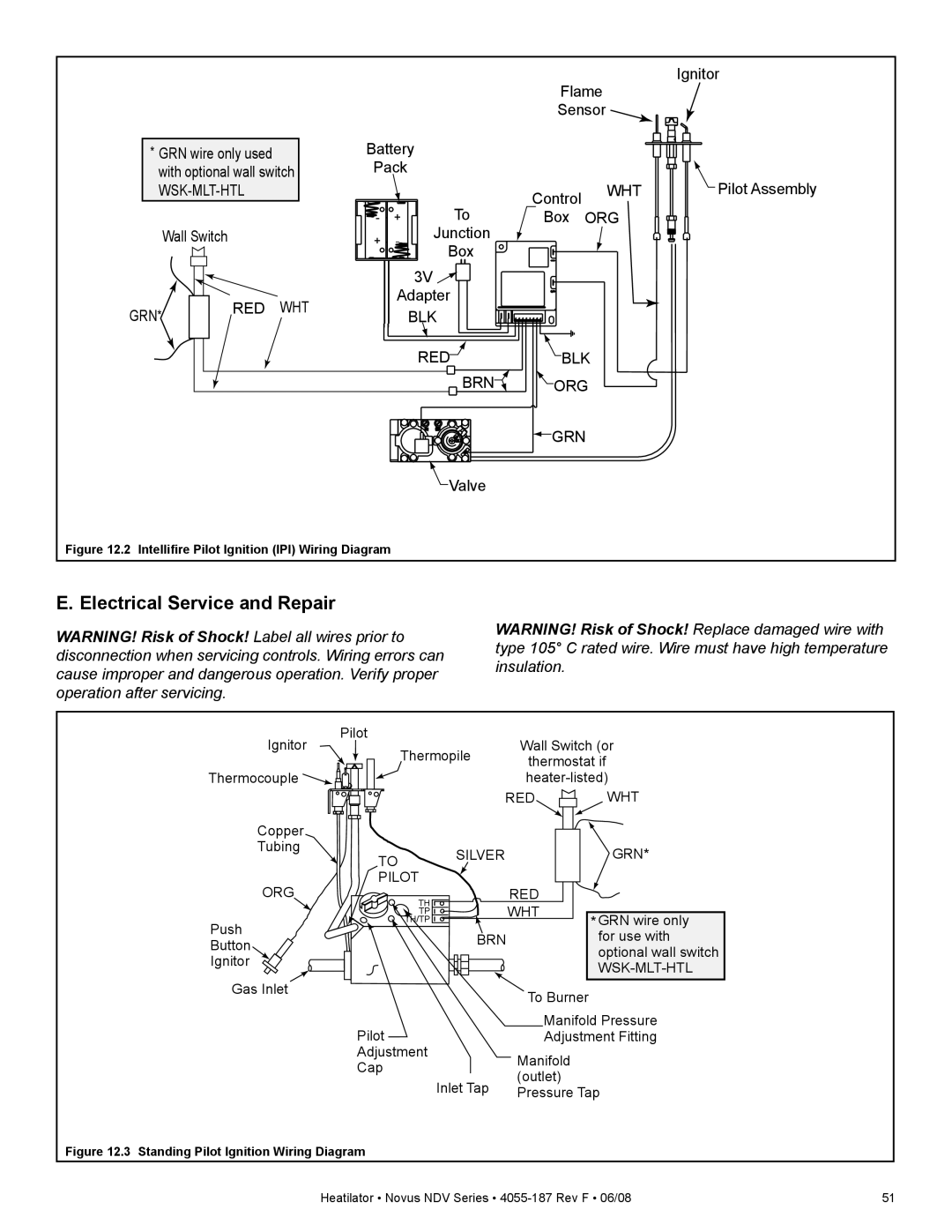
1. Pilot won’t light. The | A. Incorrect wiring. | Verify “S” wire (white) for sensor and “I” wire (orange) for ignitor are |
ignitor/module makes |
| connected to correct terminals on module and pilot assembly. |
noise, but no spark. |
|
|
| B. Loose connections or electrical | Verify no loose connections or electrical shorts in wiring from |
| shorts in the wiring. | module to pilot assembly. Verify connections underneath pilot |
|
| assembly are tight; also verify connections are not grounding out to |
|
| metal chassis, pilot burner, pilot enclosure, mesh screen if present, |
|
| or any other metal object. |
|
|
|
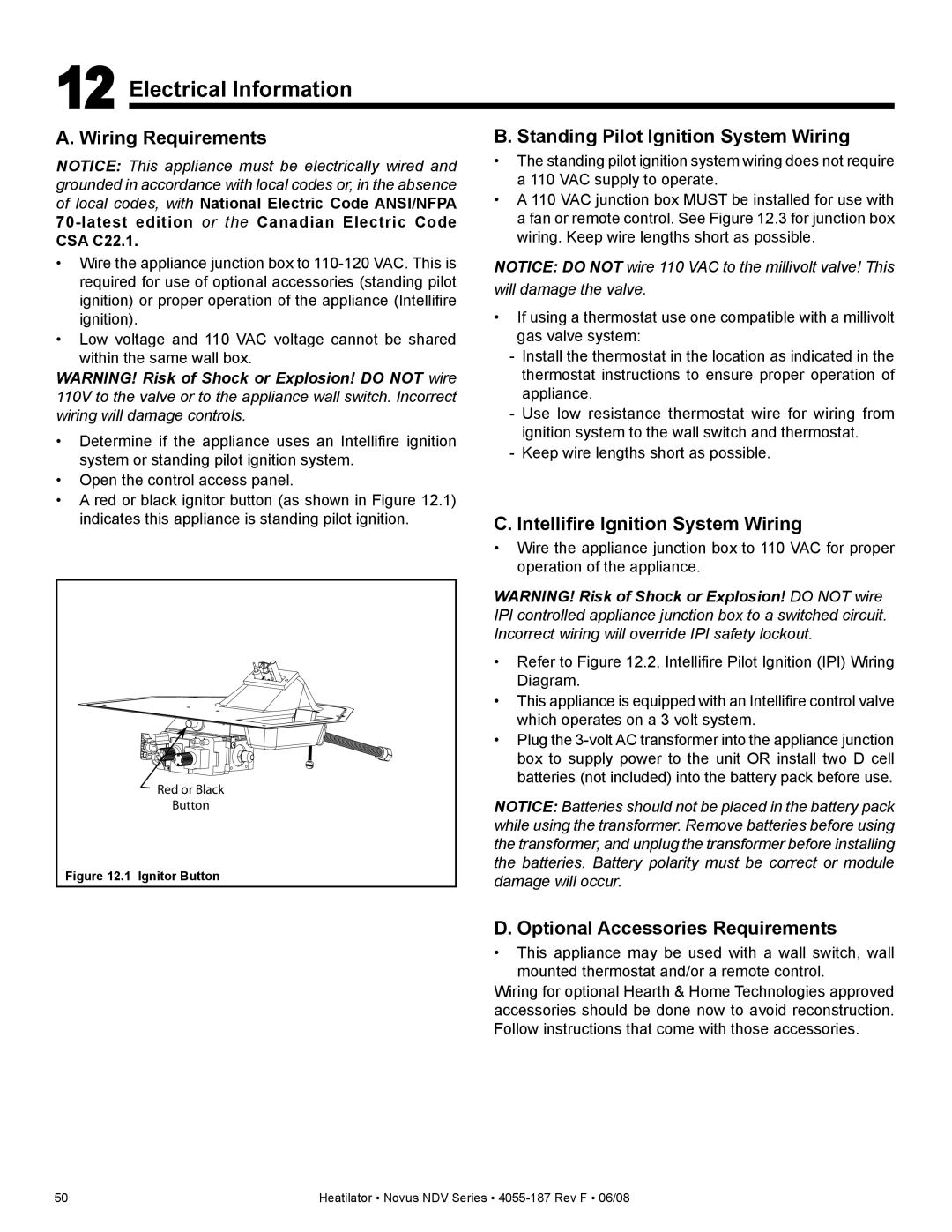
| C. Ignitor gap is too large. | Verify gap of igniter to right side of pilot hood. The gap should be |
|
| approximately .17 inch or 1/8 in. (3 mm). |
| D. Module. | Turn ON/OFF rocker switch or wall switch to OFF position. Remove |
|
| ignitor wire “I” from module. Place a grounded wire about 3/16 in. (5 |
|
| mm) away from “I” terminal on module. Place ON/OFF rocker switch |
|
| or wall switch in ON position. If there is no spark at “I” terminal |
|
| module must be replaced. If there is a spark at “I” terminal, module |
|
| is fine. Inspect pilot assembly for shorted sparker wire or cracked |
|
| insulator around electrode. Replace pilot if necessary. |
|
|
|
2. Pilot won’t light, there is no | A. No power or transformer | Verify that transformer is installed and plugged into module. Check |
noise or spark. | installed incorrectly. | voltage of transformer under load at spade connection on module |
|
| with ON/OFF switch in ON position. Acceptable readings of a good |
|
| transformer are between 3.2 and 2.8 volts AC. |
|
|
|
| B. A shorted or loose connection | Remove and reinstall the wiring harness that plugs into module. |
| in wiring configuration or wiring | Verify there is a tight fit. Verify pilot assembly wiring to module. |
| harness. | Remove and verify continuity of each wire in wiring harness. |
|
| Replace any damaged components. |
| C. Improper wall switch wiring. | Verify that 110/VAC power is “ON” to junction box. |
|
|
|
| D. Module not grounded. | Verify black ground wire from module wire harness is grounded to |
|
| metal chassis of appliance. |
| E. Module. | Turn ON/OFF rocker switch or wall switch to OFF position. Remove |
|
| ignitor wire “I” from module. Place ON/OFF rocker switch or wall |
|
| switch in ON position. If there is no spark at “I” terminal module |
|
| must be replaced. If there is a spark at “I” terminal, module is fine. |
|
| Inspect pilot assembly for shorted sparker wire or cracked insulator |
|
| around electrode. |
|
|
|
3. Pilot sparks, but Pilot will | A. Gas supply. | Verify that incoming gas line ball valve is “open”. Verify that inlet |
not light. |
| pressure reading is within acceptable limits, inlet pressure must not |
|
| exceed 14 in. W.C. |
| B. Ignitor gap is incorrect. | Verify that spark gap from ignitor to pilot hood is .17 in. or 1/8 in (3 |
|
| mm). |
| C. Module is not grounded. | Verify module is securely grounded to metal chassis of appliance. |
|
|
|
| D. Module voltage output / Valve/ | Verify battery voltage is at least 2.7 volts. Replace batteries if |
| Pilot solenoid ohms readings. | voltage is below 2.7. |
|
|
|
62 | Heatilator • Novus NDV Series • |