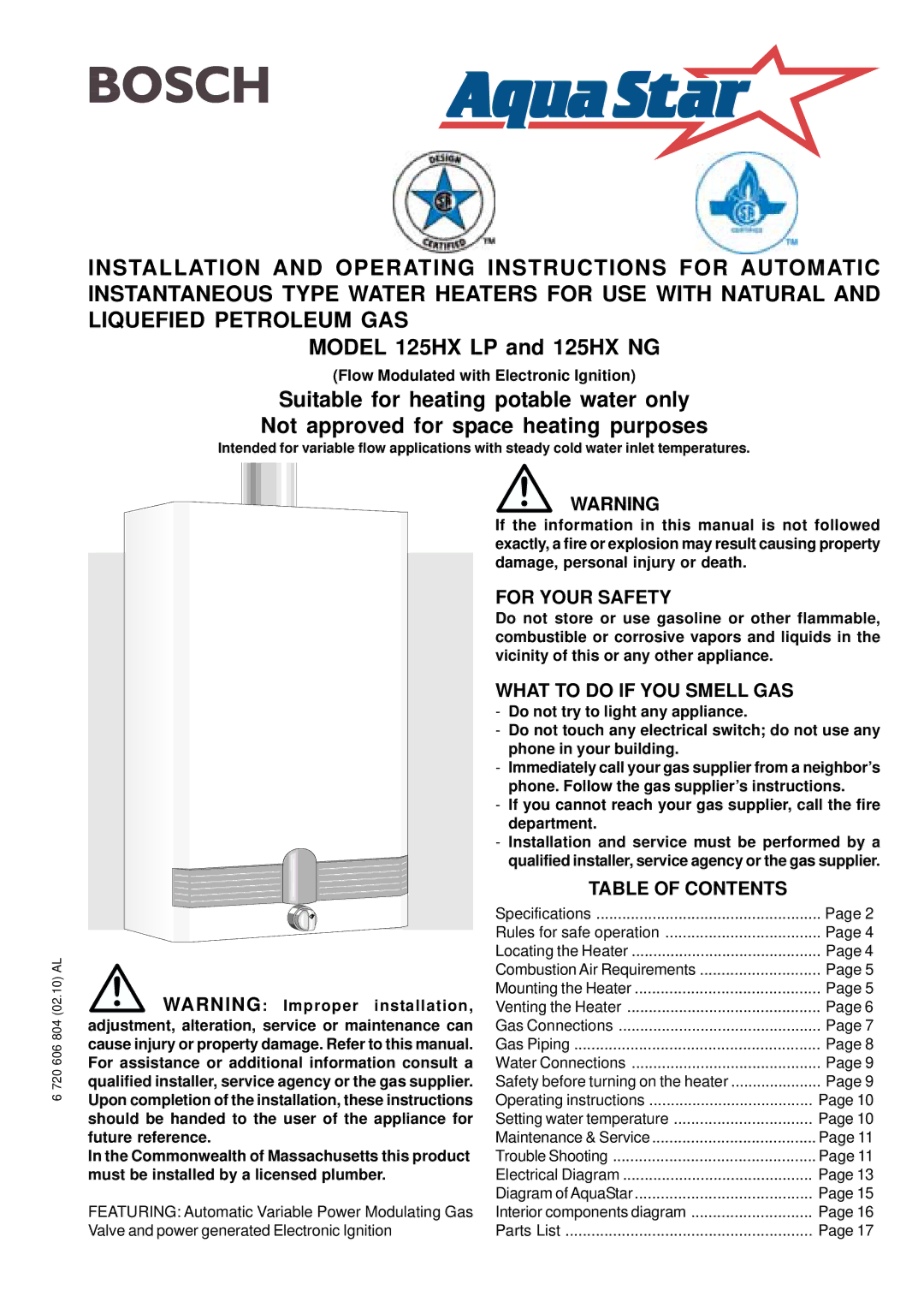
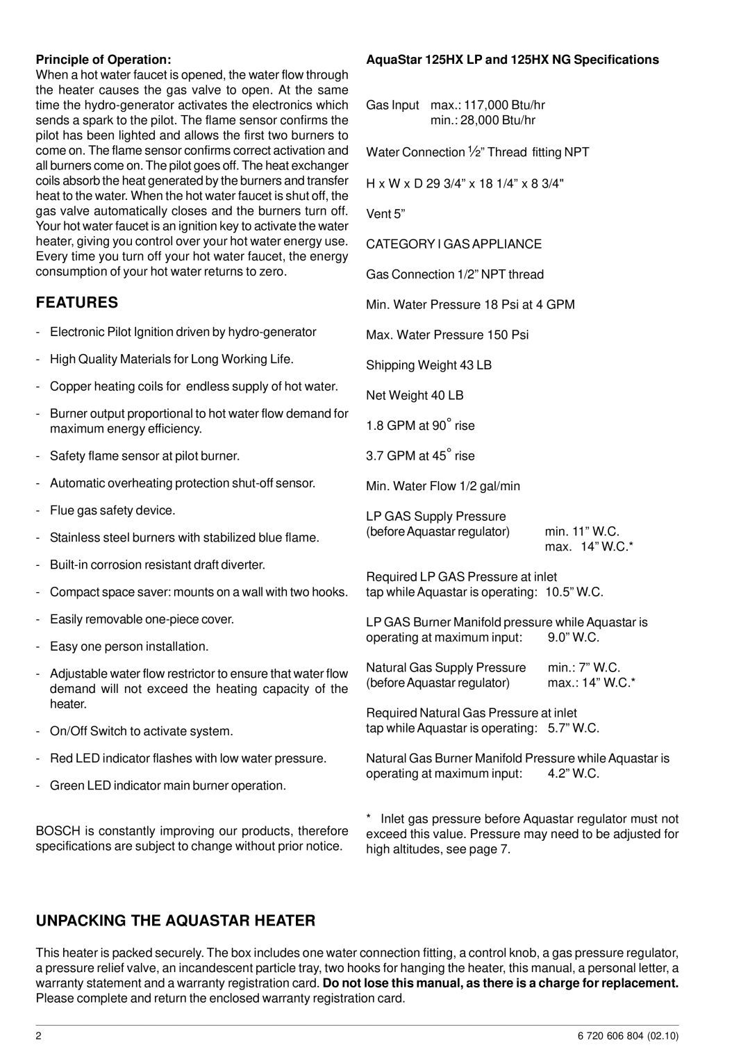
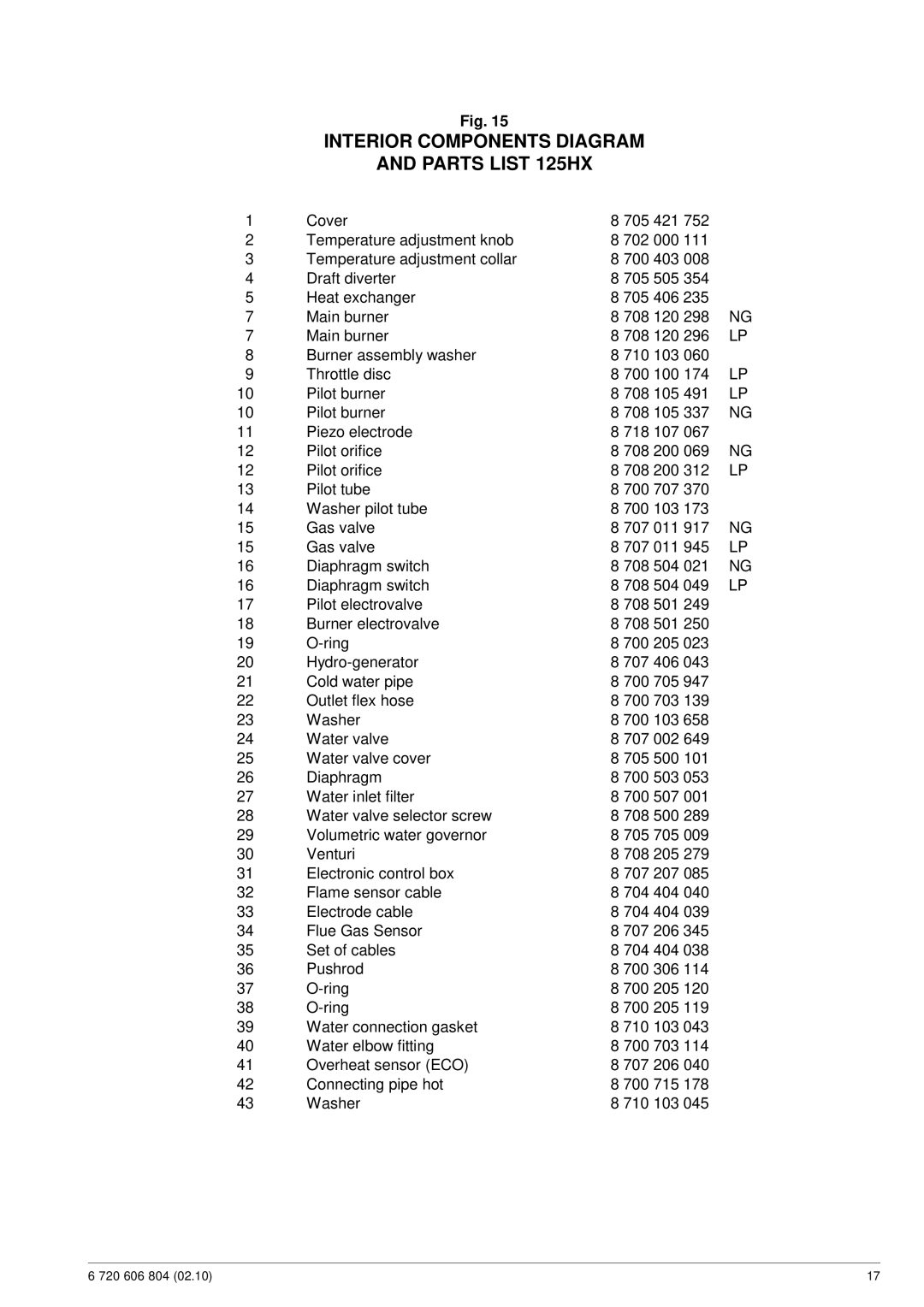
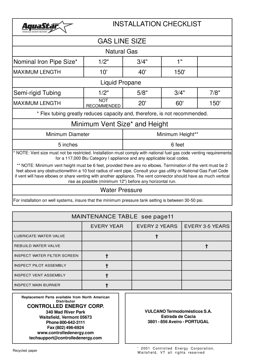
125HX NG specifications
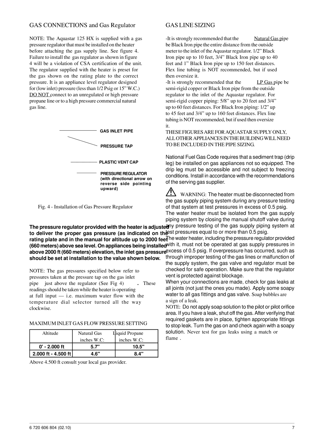
Bosch Appliances has long been synonymous with innovation and quality, and their 125HX NG model is no exception. Designed for home cooks and culinary enthusiasts alike, the Bosch 125HX NG is a natural gas cooktop that combines state-of-the-art features with unmatched performance.One of the standout features of the Bosch 125HX NG is its five powerful burners, which offer flexibility for various cooking techniques. These burners include a high-heat burner perfect for searing meats and achieving high-temperature cooking, along with a simmer burner designed for those delicate sauces and slow cooking tasks. The configuration of the burners allows for multiple pots and pans to be used simultaneously, maximizing efficiency and convenience in the kitchen.
The surface of the cooktop is constructed from premium stainless steel, offering not only a sleek aesthetic but also durability that withstands the rigors of daily cooking. The seamless design facilitates easy cleaning, ensuring that spills and stains can be wiped away with minimal effort.
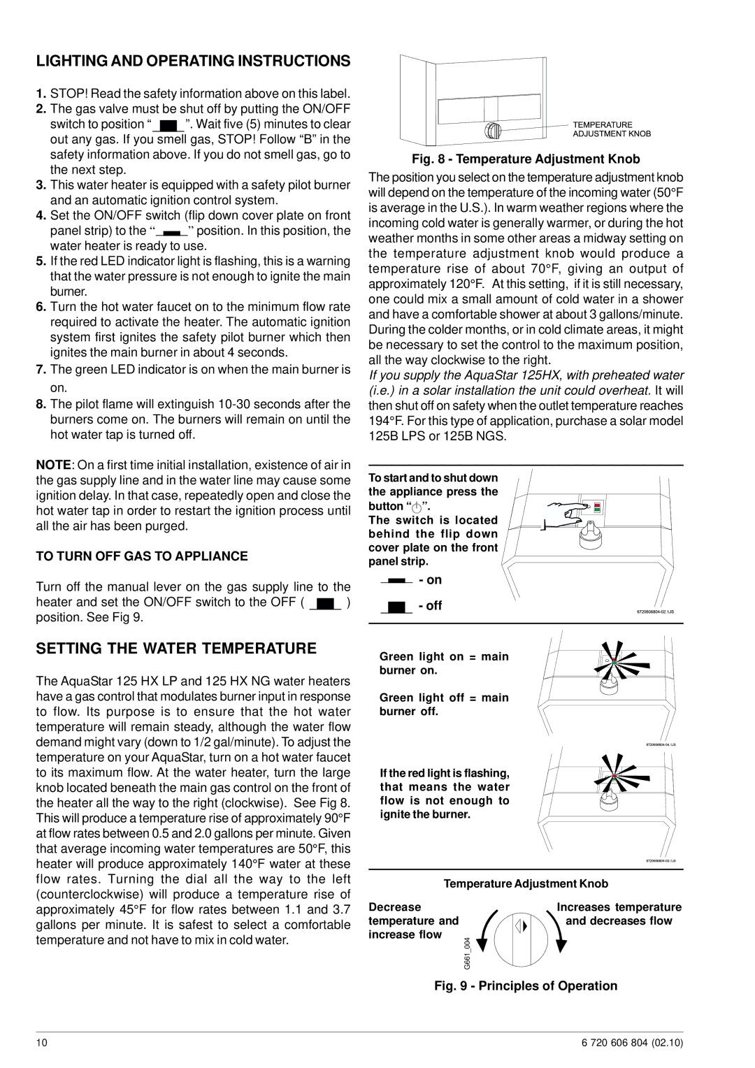
Technology plays a key role in the Bosch 125HX NG model, featuring precise temperature control and rapid ignition systems. The automatic re-ignition feature enhances safety, ensuring that the flame is reignited if it goes out unexpectedly, providing peace of mind to users while cooking.
Another notable characteristic is the cooktop’s continuous grates, which provide stability for pots and pans, allowing for effortless sliding between burners without the risk of spills. These heavy-duty grates contribute to the overall robustness of the cooktop, reinforcing Bosch’s commitment to functional design.
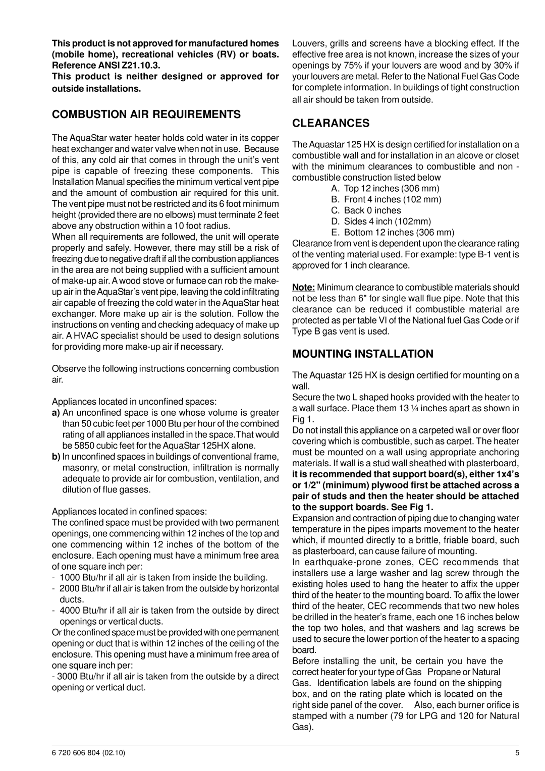
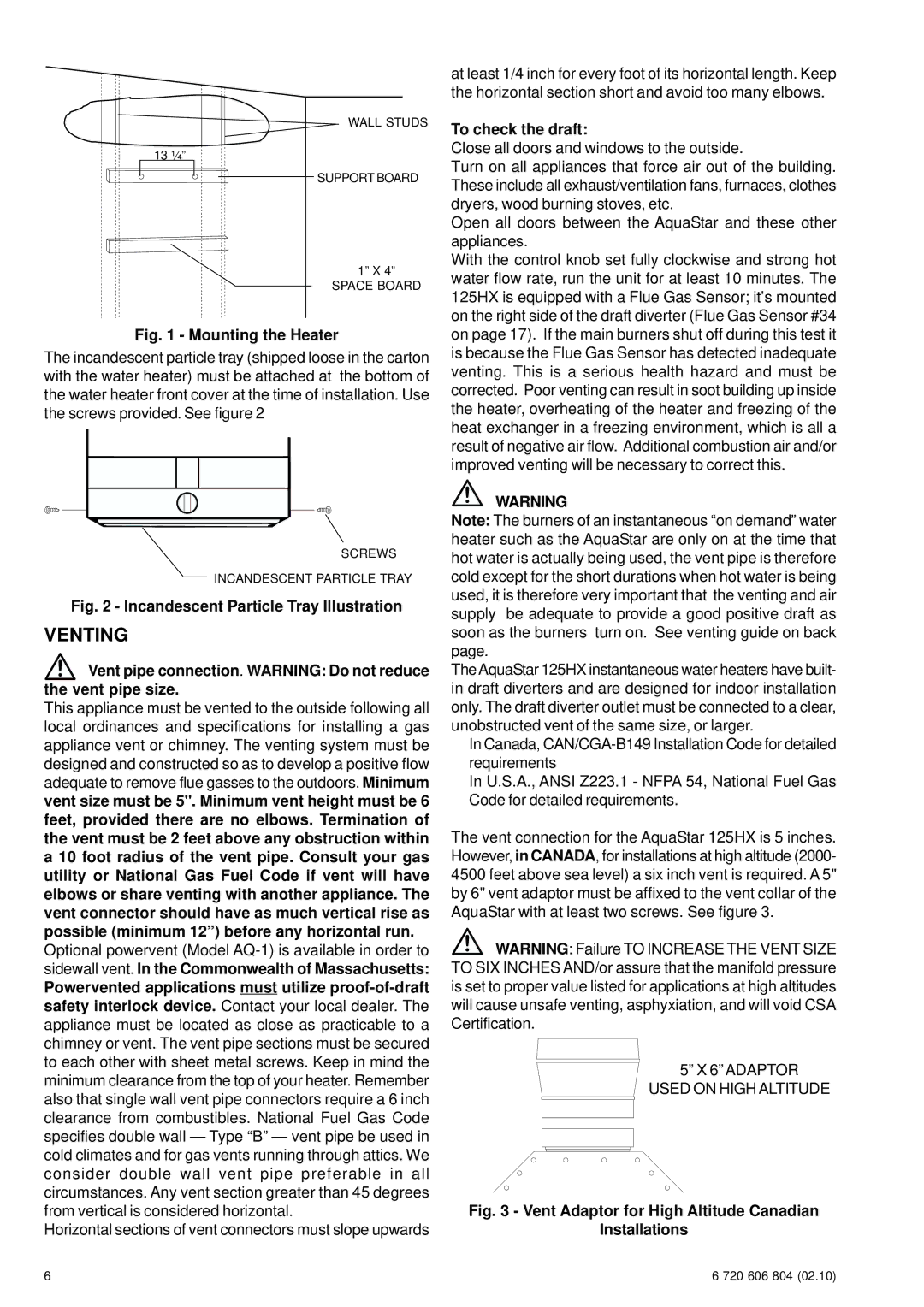
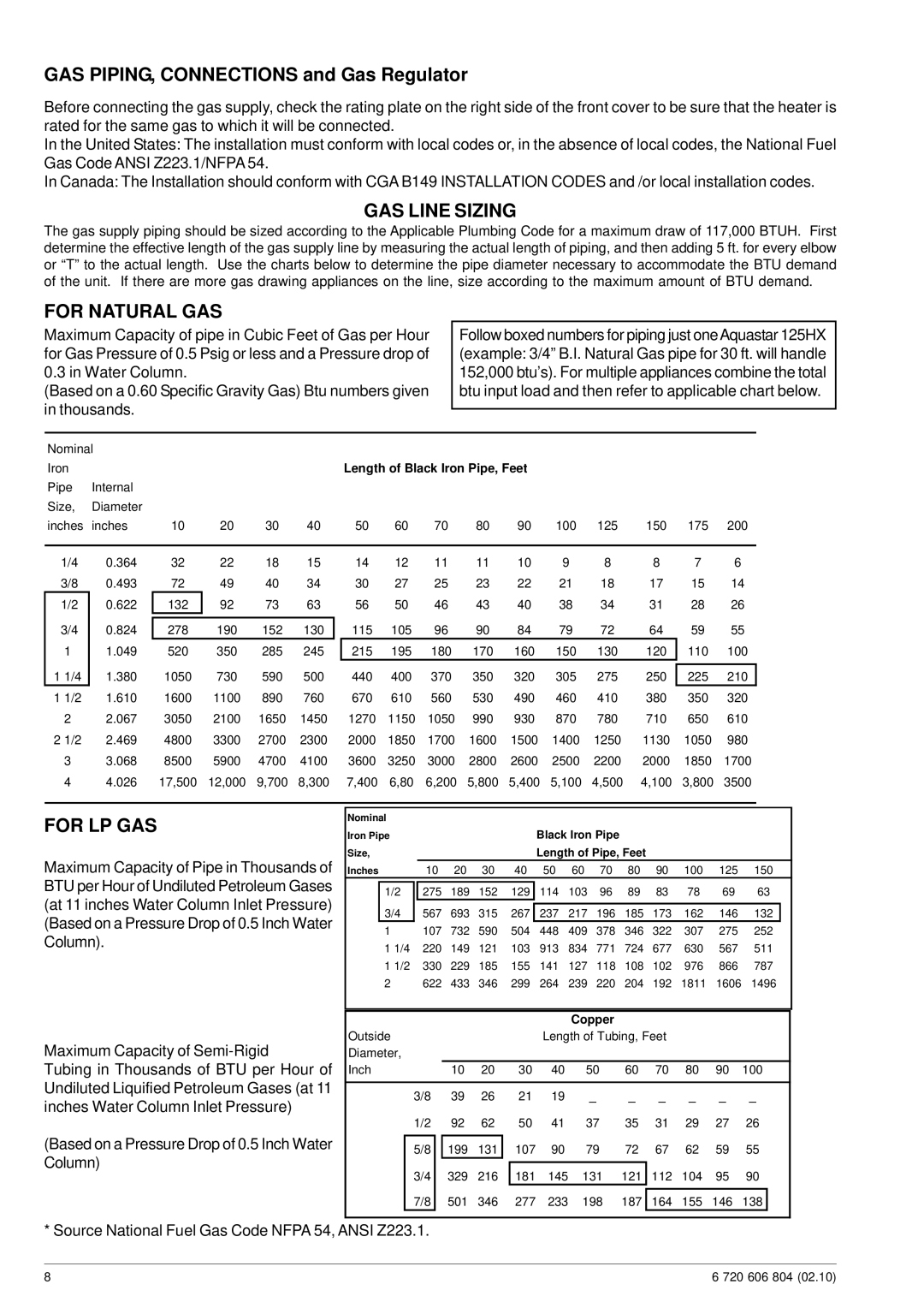
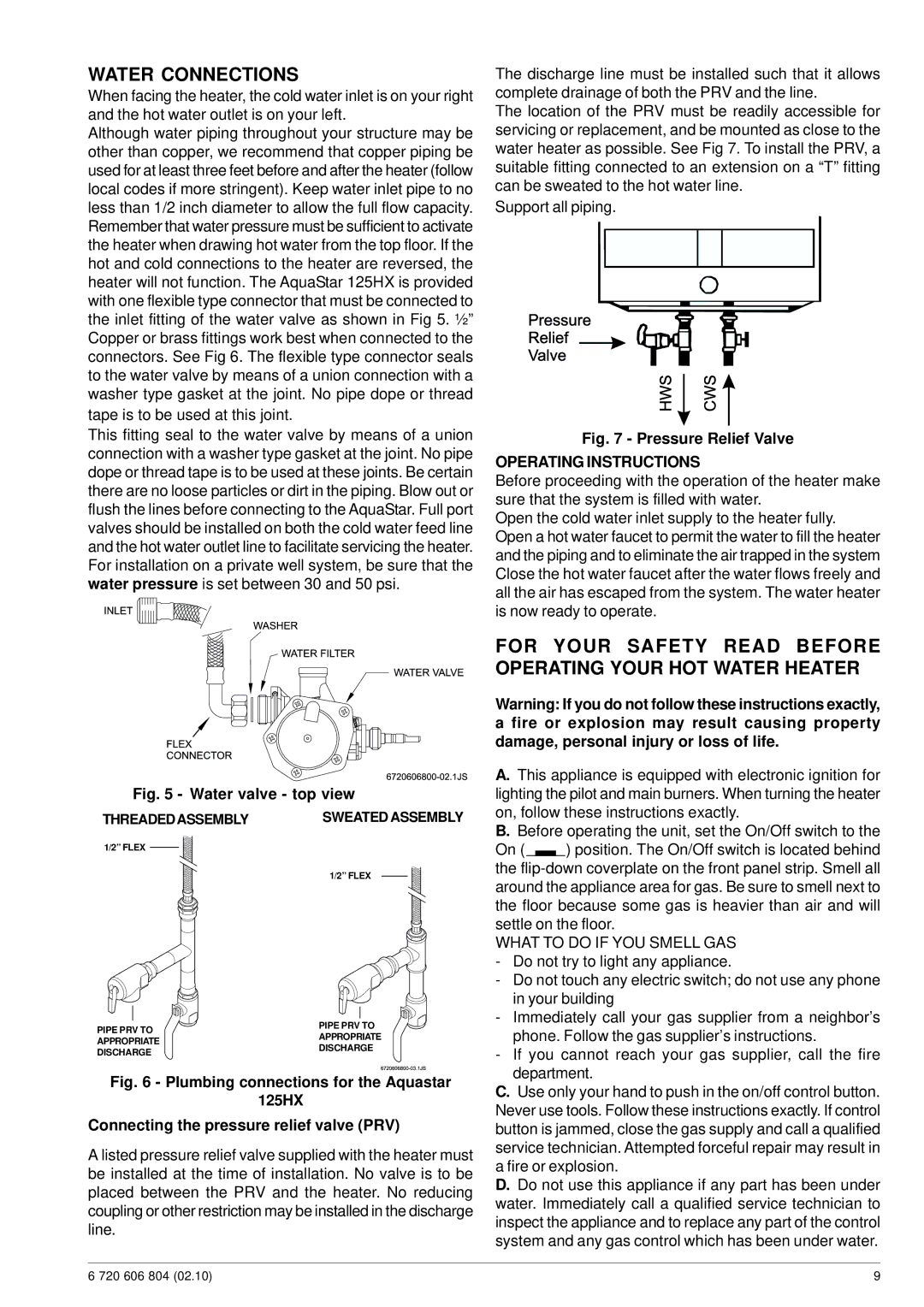
In terms of installation, the Bosch 125HX NG is compatible with various kitchen layouts, making it a versatile choice for both new builds and remodels. The model is also designed with energy efficiency in mind, helping homeowners to save on gas consumption while enjoying consistent cooking results.
Overall, the Bosch Appliances 125HX NG is a sophisticated and reliable natural gas cooktop that caters to the needs of modern cooking. With its array of features, advanced technologies, and high-quality materials, it's a perfect addition to any kitchen, appealing to both amateur cooks and seasoned chefs. Investing in a Bosch 125HX NG means enjoying durability, functionality, and style in one exceptional cooking appliance.
