Weed Eater 178106 manual Tractor - Model Number WE12538J, Schematic

Page 26

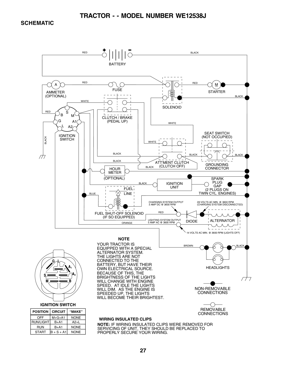
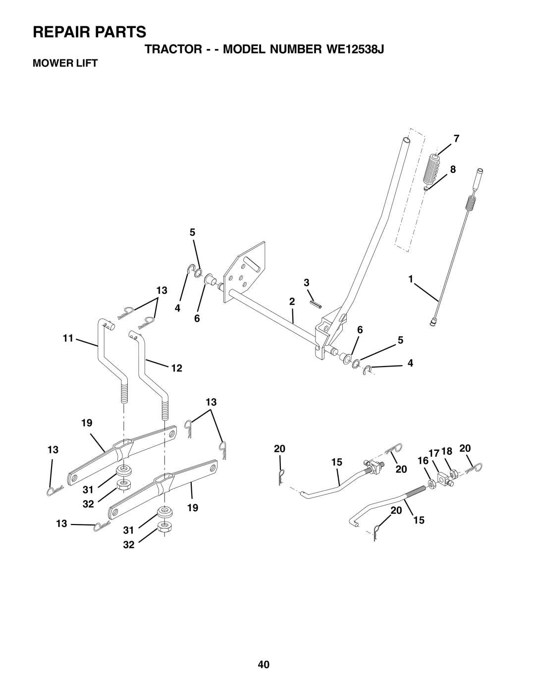
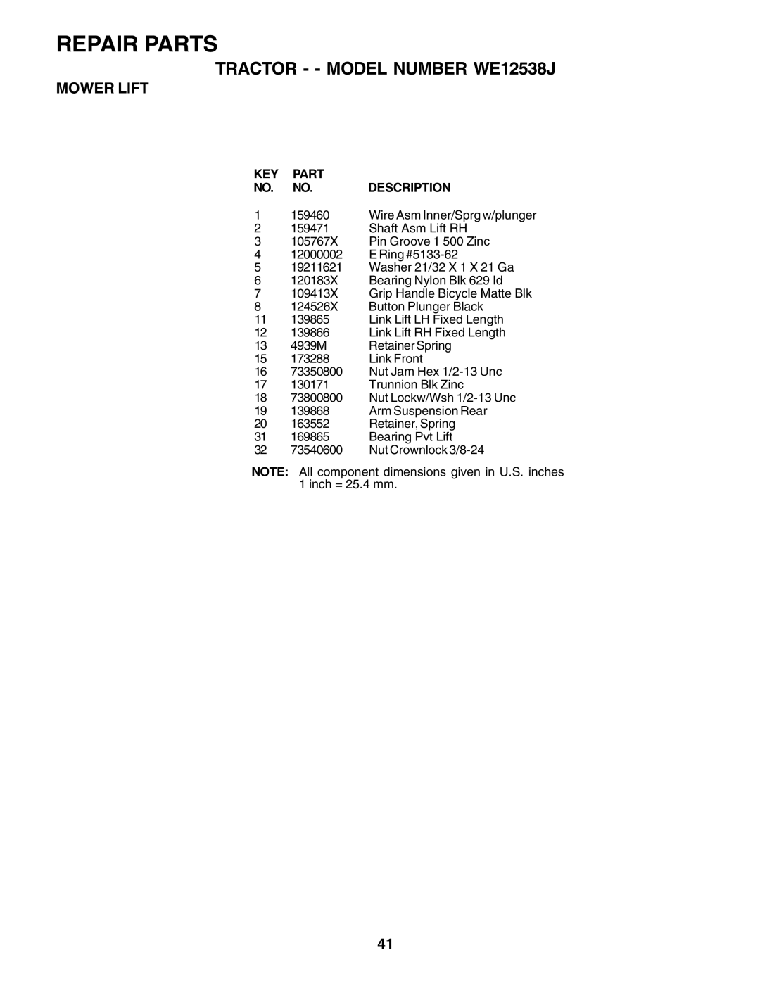
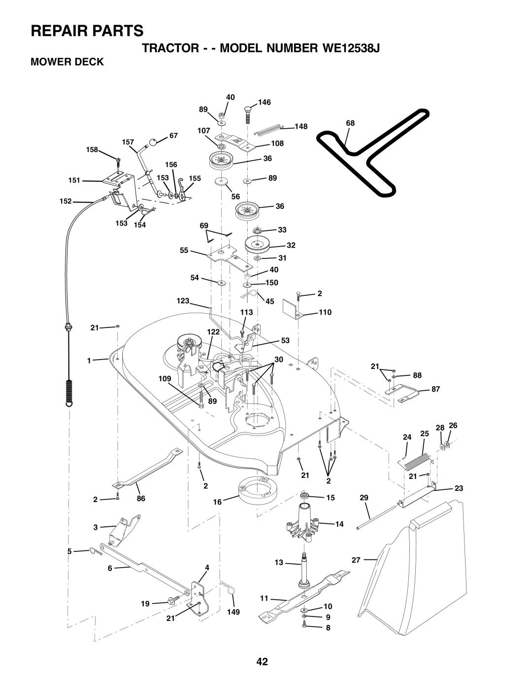
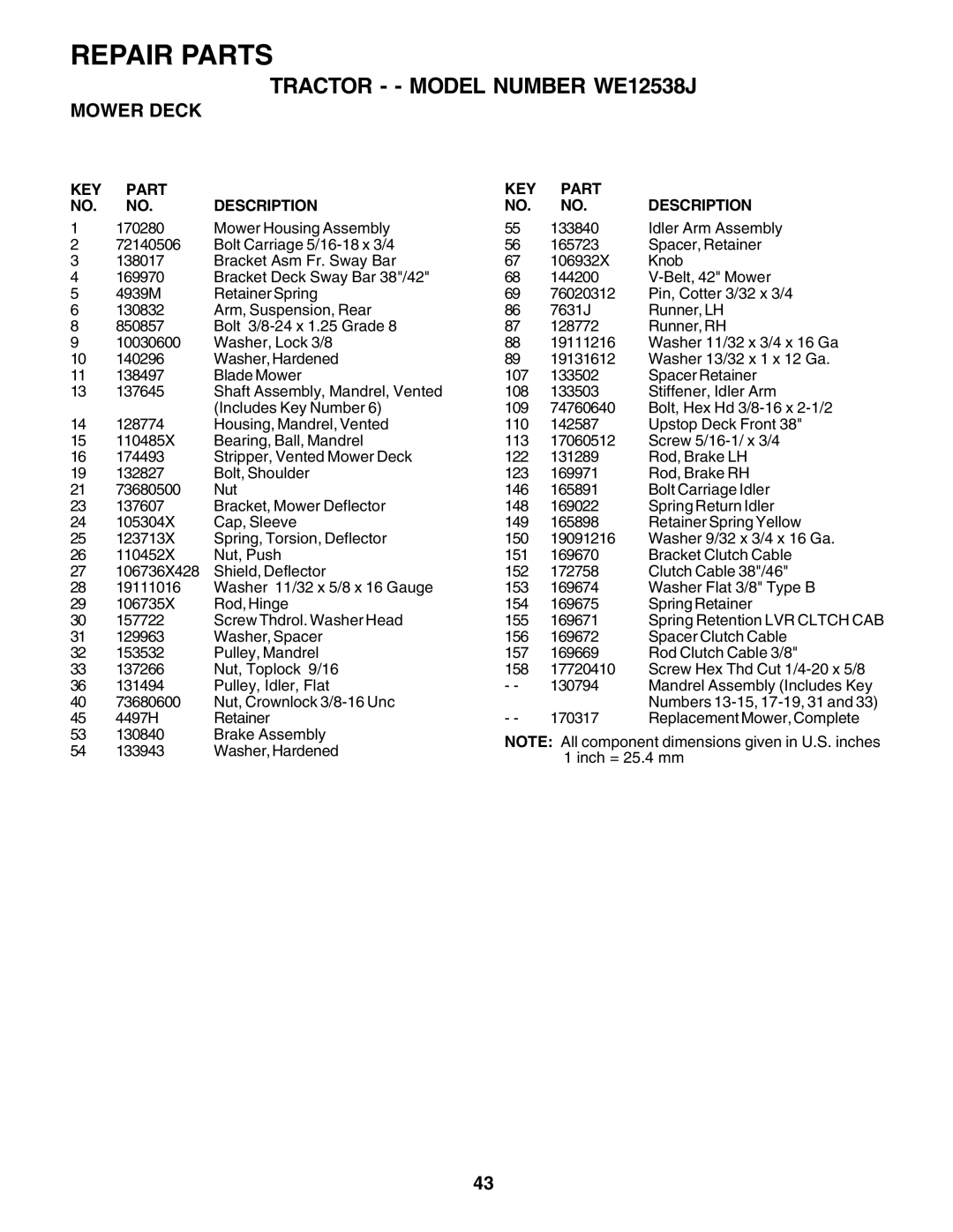
TRACTOR - - MODEL NUMBER WE12538J

SCHEMATIC

RED

BLACK

BATTERY


A

RED


AMMETER


FUSE


(OPTIONAL)


WHITE


RED

B

S


M

CLUTCH / BRAKE


G


A1

(PEDAL UP)


L

A2


BLACK

IGNITION


SWITCH


BLACK


BLACK


HOUR


METER


(OPTIONAL)


FUEL


BLUE

LINE


RED

M


STARTER


BLACK


SOLENOID


WHITE


SEAT SWITCH


(NOT OCCUPIED)

WHITE


BLACK

BLACK


ATT'MENT CLUTCH

GROUNDING

BLACK

(CLUTCH OFF)

CONNECTOR


SPARK

BLACK


IGNITION


PLUG


UNIT


GAP


(2 PLUGS ON


TWIN CYL. ENGINES)


CHARGING SYSTEM OUTPUT

28 VOLTS AC MIN. @ 3600 RPM


3 AMP DC @ 3600 RPM

(CHARGING SYSTEM DISCONNECTED)

FUEL SHUT-OFF SOLENOID

RED


(IF SO EQUIPPED)

LIGHTING SYSTEM OUTPUT


DIODE


ORANGE

5 AMP AC @ 3600 RPM


ALTERNATOR

14 VOLTS AC MIN. @ 3600 RPM (LIGHTS OFF)

IGNITION SWITCH

POSITION

CIRCUIT

“MAKE”


OFF

M+G+A1

NONE

RUN/LIGHT

B+A1

A2+L

NOTE

YOUR TRACTOR IS EQUIPPED WITH A SPECIAL ALTERNATOR SYSTEM. THE LIGHTS ARE NOT CONNECTED TO THE BATTERY, BUT HAVE THEIR OWN ELECTRICAL SOURCE. BECAUSE OF THIS, THE BRIGHTNESS OF THE LIGHTS WILL CHANGE WITH ENGINE SPEED. AT IDLE THE LIGHTS WILL DIM. AS THE ENGINE IS SPEEDED UP, THE LIGHTS

WILL BECOME THEIR BRIGHTEST.

WIRING INSULATED CLIPS

BROWN

BLACK

HEADLIGHTS

NON-REMOVABLE

CONNECTIONS

REMOVABLE

CONNECTIONS

RUN

B+A1

NONE

START

B + S + A1

NONE

NOTE: IF WIRING INSULATED CLIPS WERE REMOVED FOR SERVICING OF UNIT, THEY SHOULD BE REPLACED TO PROPERLY SECURE YOUR WIRING.

27

Image 26
Contents Model NO. WE12538J General Operation Safety RulesIV. Service II. Slope OperationSafety Rules Safe Operation Practices for Ride-On MowersTable of Contents Keys Unassembled PartsSteering Wheel Seat To Remove Tractor from Carton AssemblyTools Required for Assembly Before Removing Tractor from SkidInstall Seat See Fig HOW to SET UP Your TractorCheck Battery See Fig Check for Proper Position of ALL Belts Check Tire PressureCheck Deck Levelness Check Brake SystemOperation Know Your Tractor HOW to USE Your Tractor To USE Throttle Control see FIGBefore Starting the Engine Mowing Tips To Start Engine See FigGeneral Recommendations ¿ Lubrication ChartCustomer Responsibilities Before Each USETires TractorBrake Operation Operator Presence SystemBelts BatteryEngine Transaxle CoolingTo Service Cartridge Clean AIR ScreenTo Service PRE-CLEANER Engine Cooling Fins See FigSpark Plugs CleaningMuffler IN-LINE Fuel Filter See FigTo Remove Mower See Fig Service and AdjustmentsTo Install Mower See Fig To Replace Mower Blade Drive Belt See Fig To Level Mower HousingBelt Installation Belt RemovalTo Adjust Steering Wheel Alignment Front Wheel TOE-IN/CAMBERInterlocks and Relays Replacing Battery See FigsTo Replace Headlight Bulb To Replace FuseTo Adjust Throttle Control Cable See Fig To Remove Hood and Grill Assembly See FigTo Adjust Carburetor EngineFuel System StorageOther Engine OILTroubleshooting Points Schematic Tractor - Model Number WE12538JElectrical KEY Part NO. NO. Description Chassis KEY Part Description Drive Transaxle Steering 140044X428 Optional Equipment 170551 Control Th/ch Flag Seat LSB42 DecalsWheels & Tires LBD48Mower Lift 159460 Wire Asm Inner/Sprg w/plunger Mower Deck Repair Parts Service Notes Limited Warranty Policy Suggested Guide for Sighting Slopes for Safe Operation Page OFF