Cutting Height Adjustment Lever
Use to raise and lower the cutting deck which determines the cutting height.
Brake Pedal
Use to stop the mower’s forward or reverse motion.
Stopping Mower
•Release blade engagement pedal all the way.
•Release the "Go" Pedal and depress the brake pedal.
•When the mower comes to a complete stop, place the shift lever in neutral.
•Engage the parking brake by pulling up on the parking brake knob.
•Turn the ignition key to OFF position and remove the key.
Safety Interlock
This unit is equipped with a safety interlock system for your protection. The interlock safety switches are connected to the brake pedal, the blade engagement pedal, the shift lever, and the seat.
The purpose of the safety interlock system is threefold:
a.to prevent the engine from starting unless the brake pedal is depressed and the blade engagement pedal is disengaged;
b.to shut off the engine if the blade pedal is not disengaged when the shift lever is put into reverse; and
c.to shut the engine off when the operator leaves the seat without engaging the parking brake.
WARNING: To avoid the risk of serious injury, do not operate the rider mower if the interlock system is malfunctioning.
•Remove objects that could be thrown by the blade(s).
•Know location and function of all controls.
•Be sure blade(s) and engine are stopped before placing hands or feet near blade(s).
•Before leaving operator's position, disengage blade(s), place the shift lever in neutral, engage parking brake, shut engine off and remove key.
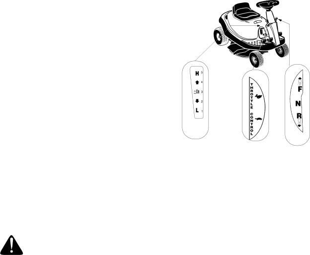
Using Shift Lever
The shift lever is used to regulate the direction of your rider mower. It can be set at forward, neutral, or reverse settings. These settings, marked as F, N,and R respectively, are located next to the shift lever on the unit. See Figure 9.
•Before you move the shift lever to any of the positions, depress the brake pedal and stop the unit. Keep your foot on the brake pedal.
CHOKE
Cutting
Height
Shift
Lever
Figure 9
•Move the lever outwards (left) to remove the locking pin from the lever and slide the lever to the position desired. Look at the rear and make sure the path is free of obstacles before positioning the shift lever to the reverse.
•Do not force the shift lever. If it does not shift, release the brake pedal slightly to line up the shifting collar in the transmission, then try to move the shift lever.
•Slowly release the brake pedal and take your foot off the pedal. Always make sure that there is no one in the way when you run the mower.
Grass Fill Level Indicator
This indicator was designed to add convenience to your riding mower. While the mower is running, air will flow through the discharge chute and into the grass catcher. If the grass catcher is empty, air flows through easily pushing the ball up. If the grass catcher is full, air does not flow through it allowing the ball to fall. So if you see the ball in the grass catcher fill level indicator falling down, you should stop the mower and empty the bag.
10