Multiquip
DCA70US13CAN
manual
Generator Wiring Diagram
Page 45
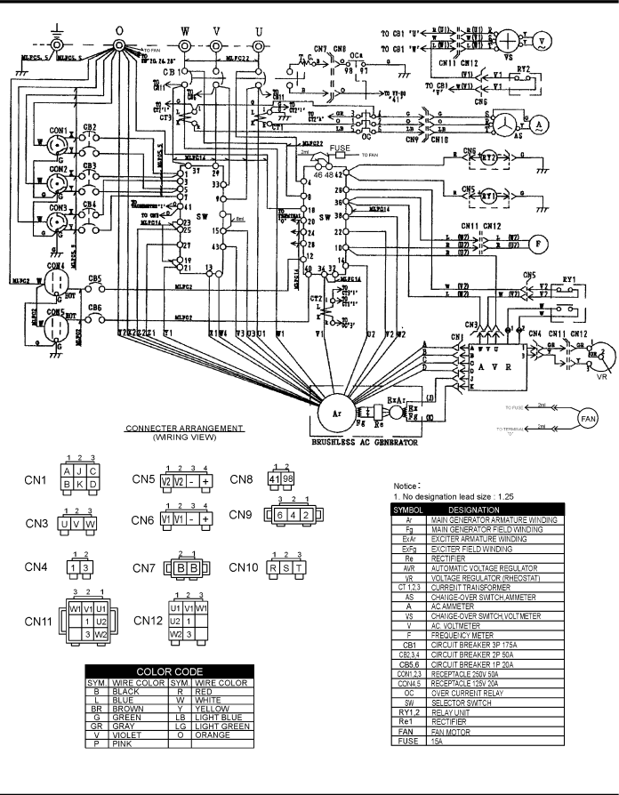
Generator Wiring Diagram
Figure 63. Generator Wiring Diagram
DCA70USI3can 60 hz Generator • operation and parts manual — rev. #1 (09/24/13) — page 45
Page 44
Page 46
Image 45
Page 44
Page 46
Contents
Model dca70USI3CAN
Parts List NO. M2870400304C m2874400004
Fuel and chemical warning
Administrator
Reporting Safety Defects
DCA70USI3CAN Generator
Table of Contents
Choose from three easy options
Safety Information
SaFetY meSSageS
SaFetY SYmBolS
Generator Safety
General SaFetY
If operating in speed ranges above the maximum allowable
Restricted. If the air fl ow is
FUel SaFetY
„ never use fuel as a cleaning agent
From fuel vapors or if fuel is spilled on a hot engine
Power Cord/Cable Safety
EleCtrICal SaFetY
Grounding Safety
BatterY SaFetY
EmISSIonS InFormatIon
EnvIronmental SaFetY/DeCommISSIonIng
Emission Control label
Label must remain with the engine for its entire life
Specifications
Model
Isuzu BJ-4JJ1XYGD-02 Tier
Dimensions
Dimensions
Typical Generator Grounding Application
Installation
Indoor Installation
Outdoor Installation
Mounting
Generator Grounding
General Information
Item no
Major Components
OFF
Generator Control Panel
Page
Engine Operating Panel
Engine Operating Panel
Output Terminal Familiarization
Terminal legs O and Ground are considered bonded grounds
Output Terminal Panel is provided with the following
VAC Gfci Receptacles
Removing the Plastic Face Plate Hard Wire Hookup Panel
Over Current Relay
Connecting Loads
Three Phase Load
Single Phase Load
Load Application
Type of Load
Voltage Selector Switch Locking Button
Voltage Selector Switch
Generator Output Voltages
Generator Amperage
Generator OUTPUTS/gauge reading
How to Read the ac ammeter and ac voltage gauges
AC Voltmeter Gauge Reading
AC Ammeter Gauge Reading
Uvwo Terminal Output Voltages
3Ø-240/139 Uvwo Terminal Output Voltages
3Ø-208V/1Ø-120V Uvwo Terminal Output Voltages
1Ø-240/120V Uvwo Terminal Output Voltages
3Ø-480/277V Uvwo Terminal Output Voltages
Circuit Breakers
Inspection/SETUP
Lubrication Oil
Fuel Check
Only use #2 diesel fuel when refueling
Refueling Procedure
Air Cleaner Fan Belt Tension
Cleaning the Radiator
Coolant Antifreeze/Summer Coolant/ Water
Operation in Freezing Weather
Battery Cable Installation
Battery
Wiring
Alternator
Before Starting
Place the engine speed switch in the LOW down position
Starting
Starting Manual
Engine Speed Switch High
Emergency Shutdown Procedure
Normal Shutdown Procedure
OFF/RESET position
Place the Mpec Control Switch
Maintenance
General Inspection Air Cleaner
Air Cleaner with Dust Indicator
Fuel Addition
Cleaning Inside the Fuel Tank
Removing Water from the Fuel Tank
Fuel Tank Inspection
Check Oil Level
Radiator Cleaning
Replacing Oil Filter
Flushing Out Radiator and Replacing Coolant
Trailer Maintenance
Trailer Maintenance
Coupler Type of hitch used on the trailer for towing
Brakes
Brake Adjustment
Hydraulic Surge Brakes
Actuator
Tires/Wheels/Lug Nuts
Tire Wear/Inflation
Suspension
Never use an pneumatic air gun to tighten wheel lug nuts
Lug Nut Torque Requirements
Trailer/Towing Vehicle Wiring Diagram
Trailer Wiring Diagram
Generator Wiring Diagram
Generator Wiring Diagram
Engine Wiring Diagram
Engine Wiring Diagram
Engine Controller
Controller Wiring Diagram
Symptom Possible Problem Solution
Troubleshooting Generator
Method of Operation
Troubleshooting Diagnostic lamp
Explanation of Code in Remarks Column
Suggested Spare Parts
To 3 units
Qty Description
Generator Assy
0601820083
B5110000402
0601822664
B3120100804
Control box Assy
0330000180
M2214000302
0330000610
0330000045
Control box Assy
5825500290
8970119490
M2213500604
M2270100204
Control box Assy
0601810141
0602125090
0601831395
M1224100104
Engine and Radiator Assy
8980388560
M2923200134
8980188580
0605000451
Engine and Radiator Assy
0605515149
0191500680
M3326200204
001698020
Output Terminal Assy
M9220100304
M3230700003
M9220100404
0039316000
Battery Assy
M9310500014
0602220199
M9103000304
0602220920
Muffler Assy
0017112030
M2330101103
M2333001403
M2333200404
Fuel Tank Assy
0605501079
M2363001202
0605516090
M2363200704
Enclosure #1 Assy
M2363300603
M2413002002
0603306797
M2423001702
Enclosure ASSY. #1
35A 0030014000
0010114040
35B 0040014000
35C 0041214000
Enclosure 2 Assy
M2493305103
M2443001202
M2443301803
M2493305904
Rubber Seals Assy
REMArks
Nameplate and Decals Assy
EE57067
EE57066
M1550002203
M15000220
Nameplate and Decals Assy
M92010040
M9520100404
33A#
MQS-2731CE
Freight Policy
Terms and Conditions of Sale Parts
Page
HERE’S HOW to GET Help
Related pages
Where can I find troubleshooting tips for my
Samsung UE49K6300AKXZF
?
Top
Page
Image
Contents