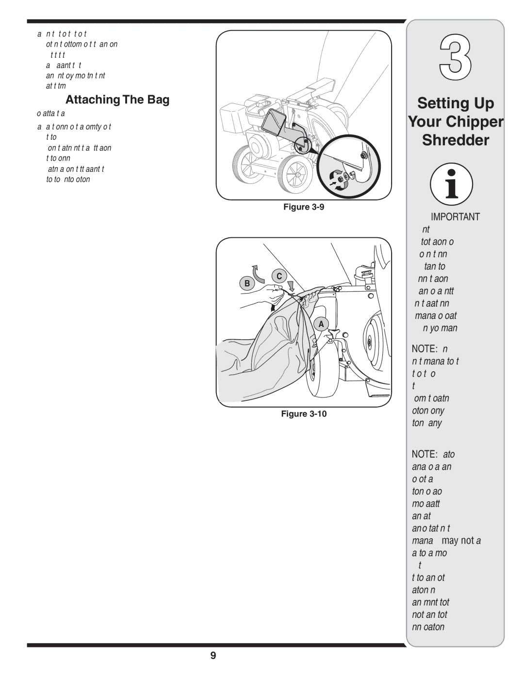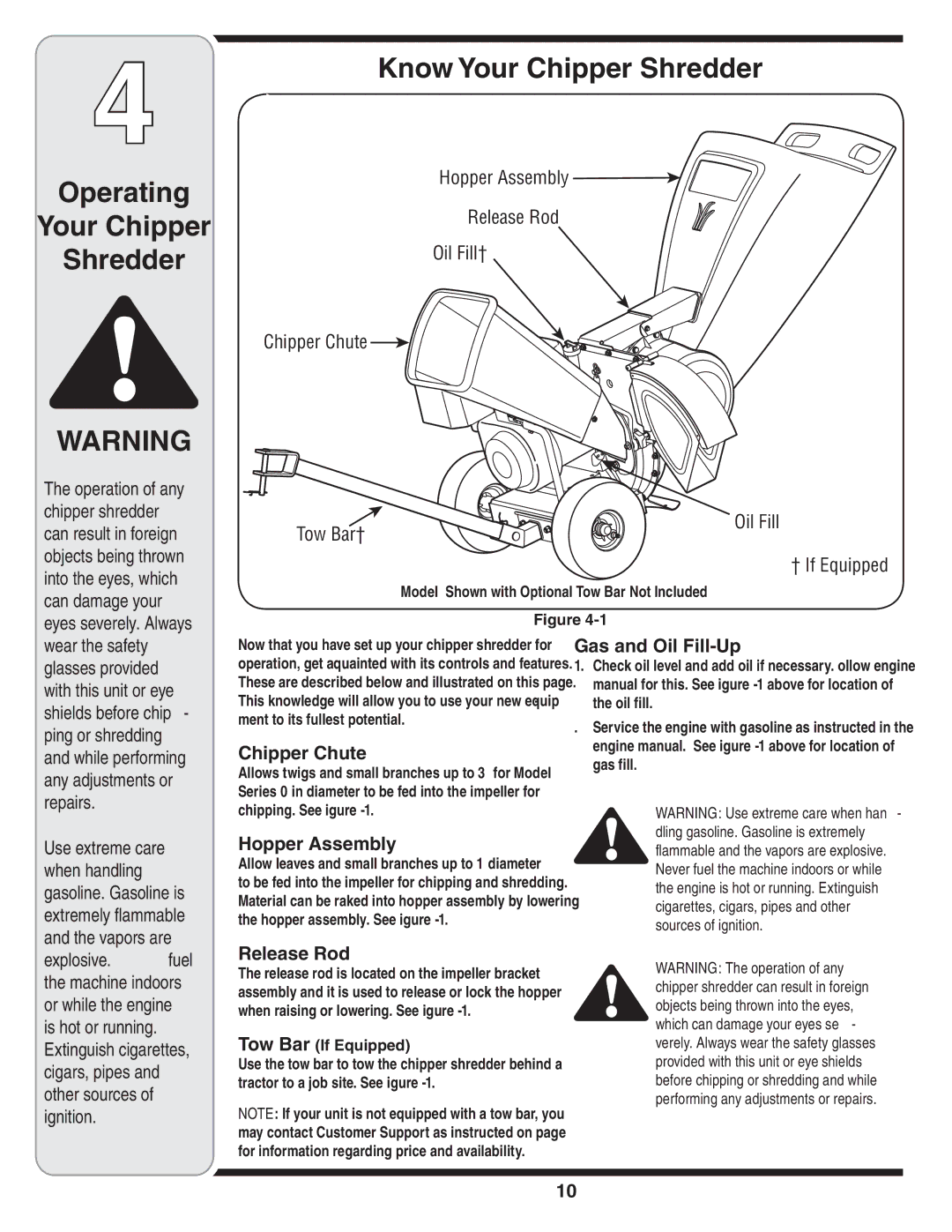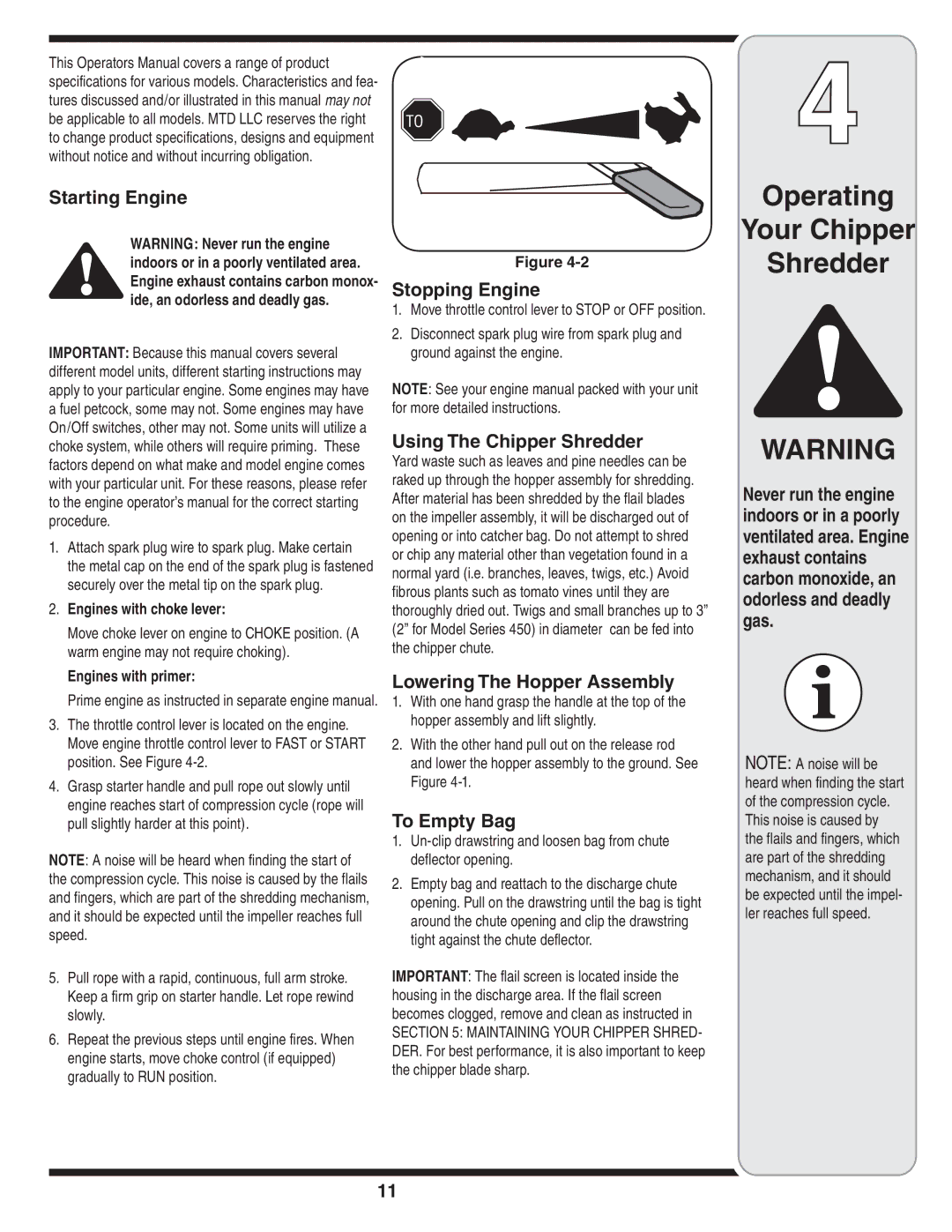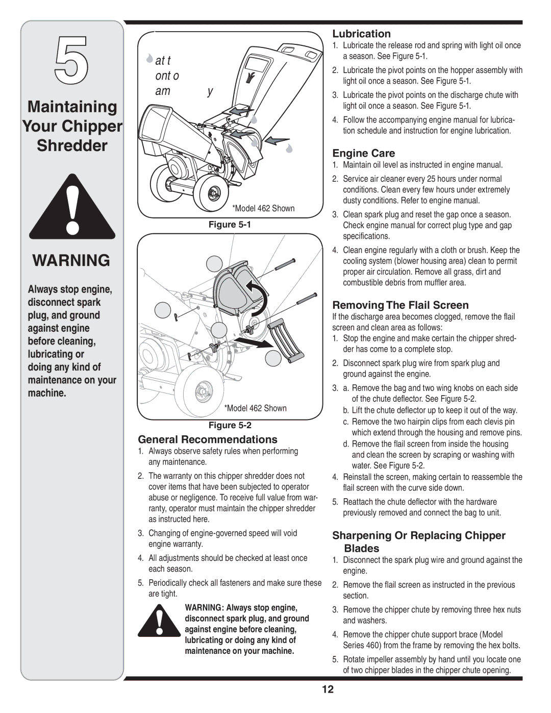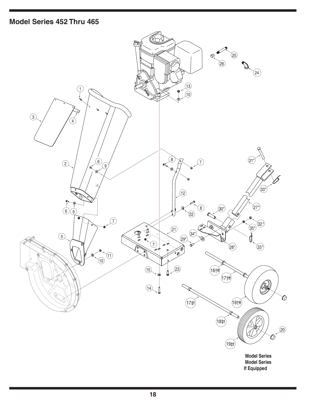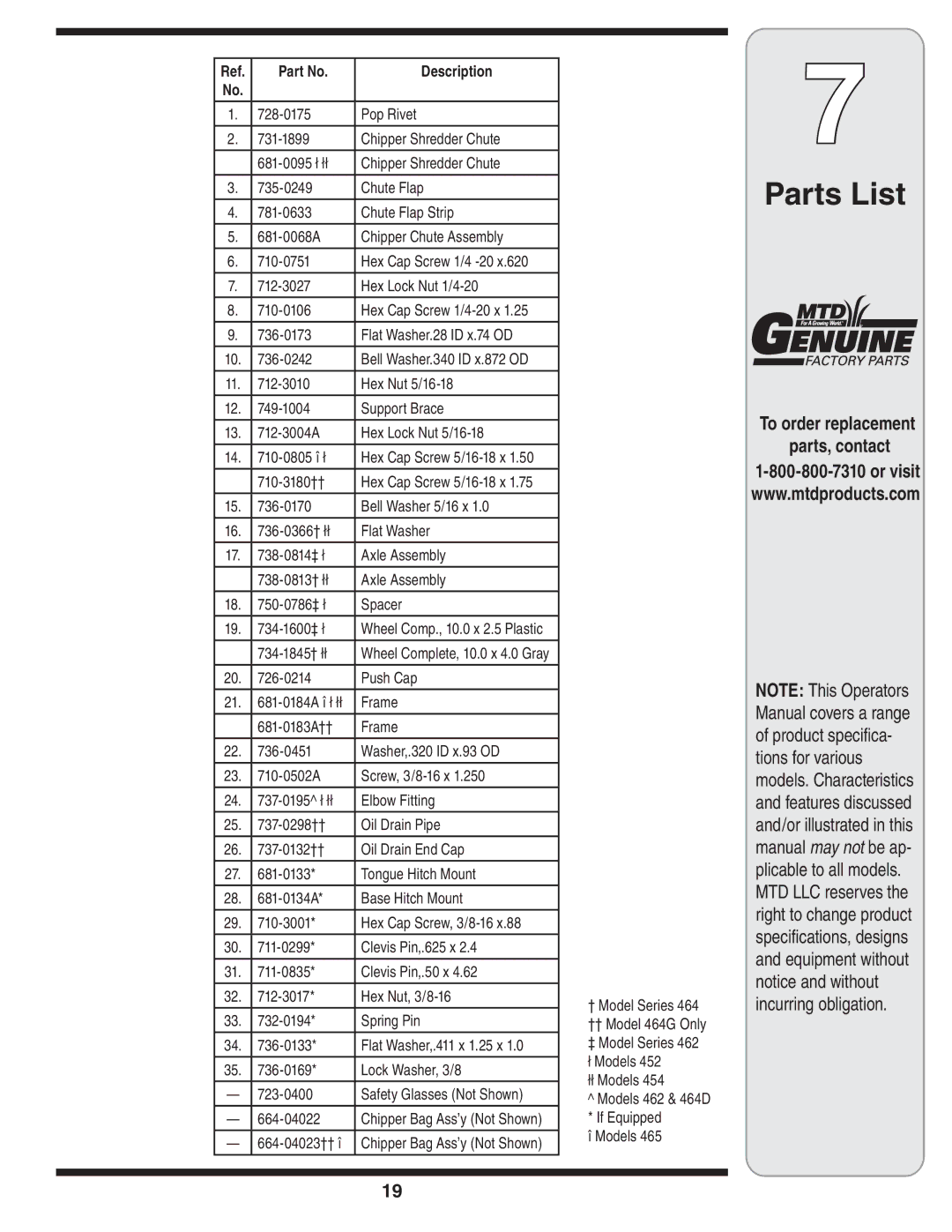
| Ref. | Part No. | Description |
|
| No. |
|
|
|
|
|
|
|
|
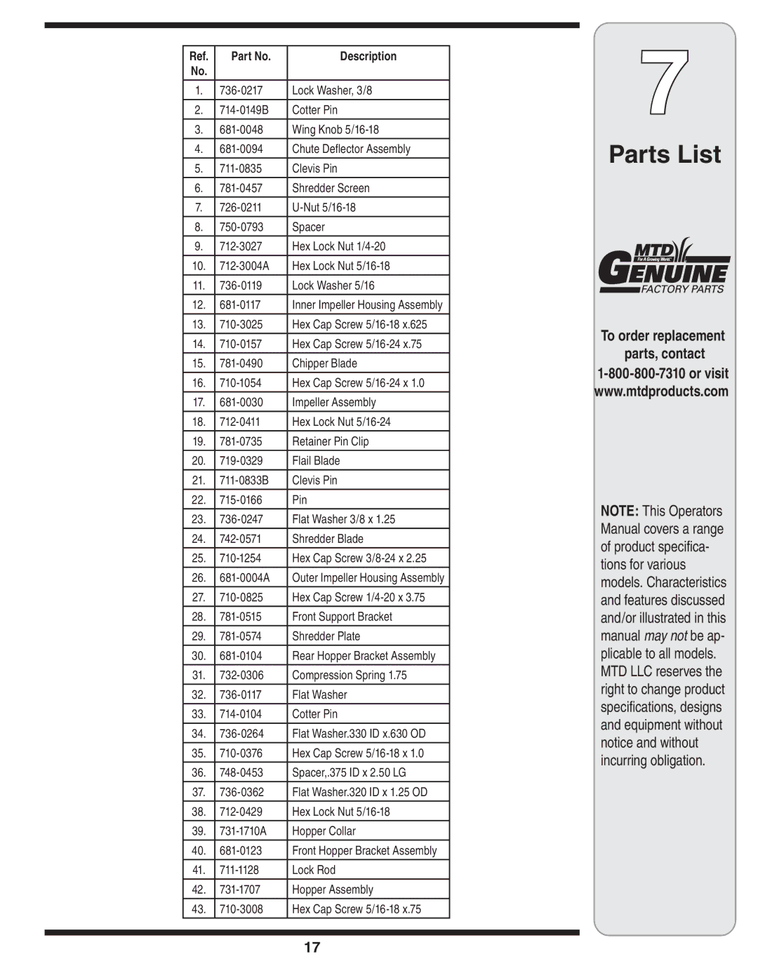
| 1. | Lock Washer, 3/8 |
| |
|
|
|
|
|
| 2. | Cotter Pin |
| |
|
|
|
|
|
| 3. | Wing Knob |
| |
|
|
|
|
|
| 4. | Chute Deflector Assembly |
| |
|
|
|
|
|
| 5. | Clevis Pin |
| |
|
|
|
|
|
| 6. | Shredder Screen |
| |
|
|
|
|
|
| 7. |
| ||
|
|
|
|
|
| 8. | Spacer |
| |
|
|
|
|
|
| 9. | Hex Lock Nut |
| |
|
|
|
|
|
| 10. | Hex Lock Nut |
| |
|
|
|
|
|
| 11. | Lock Washer 5/16 |
| |
|
|
|
|
|
| 12. | Inner Impeller Housing Assembly |
| |
|
|
|
|
|
| 13. | Hex Cap Screw |
| |
|
|
|
|
|
| 14. | Hex Cap Screw |
| |
|
|
|
|
|
| 15. | Chipper Blade |
| |
|
|
|
|
|
| 16. | Hex Cap Screw |
| |
|
|
|
|
|
| 17. | Impeller Assembly |
| |
|
|
|
|
|
| 18. | Hex Lock Nut |
| |
|
|
|
|
|
| 19. | Retainer Pin Clip |
| |
|
|
|
|
|
| 20. | Flail Blade |
| |
|
|
|
|
|
| 21. | Clevis Pin |
| |
|
|
|
|
|
| 22. | Pin |
| |
|
|
|
|
|
| 23. | Flat Washer 3/8 x 1.25 |
| |
|
|
|
|
|
| 24. | Shredder Blade |
| |
|
|
|
|
|
| 25. | Hex Cap Screw |
| |
|
|
|
|
|
| 26. | Outer Impeller Housing Assembly |
| |
|
|
|
|
|
| 27. | Hex Cap Screw |
| |
|
|
|
|
|
| 28. | Front Support Bracket |
| |
|
|
|
|
|
| 29. | Shredder Plate |
| |
|
|
|
|
|
| 30. | Rear Hopper Bracket Assembly |
| |
|
|
|
|
|
| 31. | Compression Spring 1.75 |
| |
|
|
|
|
|
| 32. | Flat Washer |
| |
|
|
|
|
|
| 33. | Cotter Pin |
| |
|
|
|
|
|
| 34. | Flat Washer.330 ID x.630 OD |
| |
|
|
|
|
|
| 35. | Hex Cap Screw |
| |
|
|
|
|
|
| 36. | Spacer,.375 ID x 2.50 LG |
| |
|
|
|
|
|
| 37. | Flat Washer.320 ID x 1.25 OD |
| |
|
|
|
|
|
| 38. | Hex Lock Nut |
| |
|
|
|
|
|
| 39. | Hopper Collar |
| |
|
|
|
|
|
| 40. | Front Hopper Bracket Assembly |
| |
|
|
|
|
|
| 41. | Lock Rod |
| |
|
|
|
|
|
| 42. | Hopper Assembly |
| |
|
|
|
|
|
| 43. | Hex Cap Screw |
| |
|
|
|
|
|
|
|
|
|
|
|
|
|
|
|
7
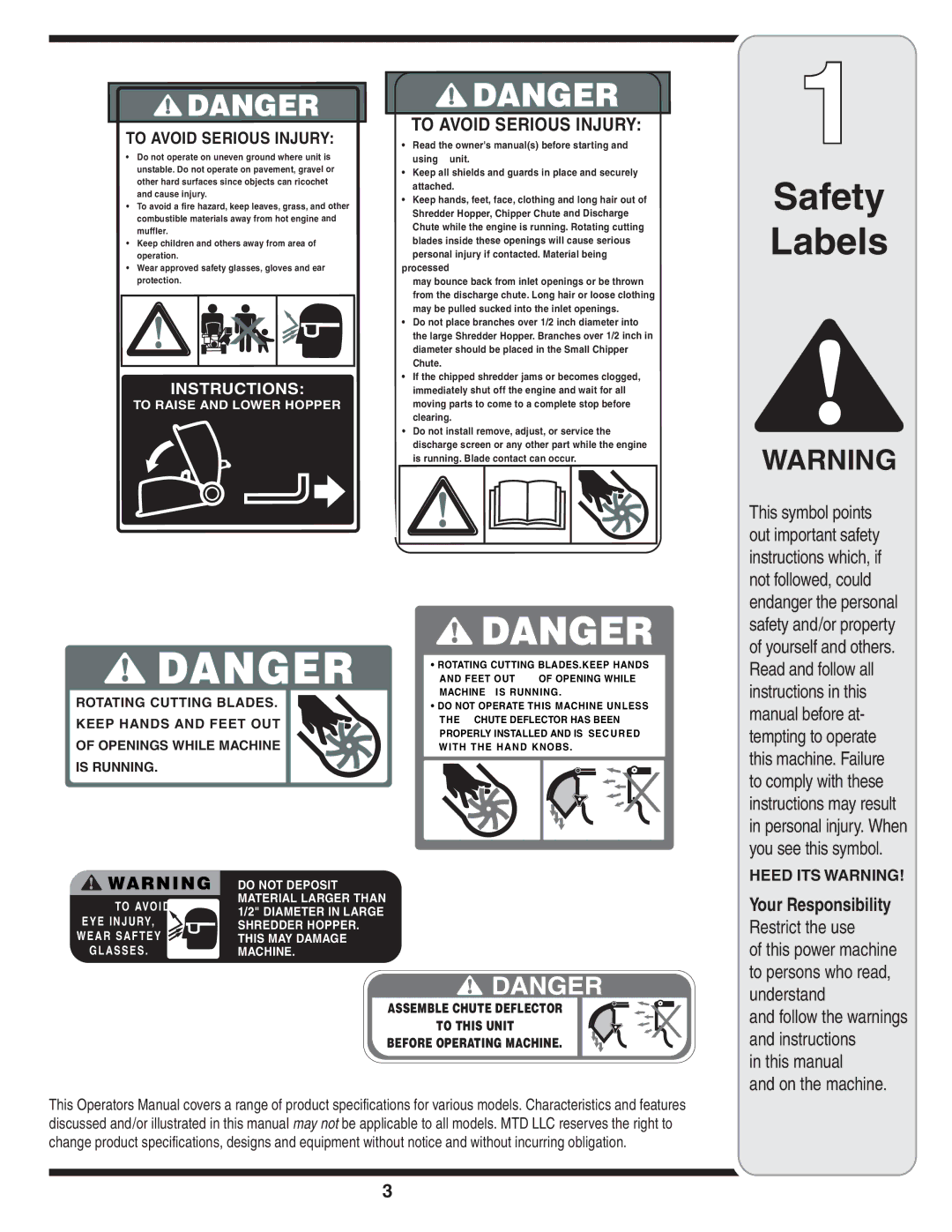
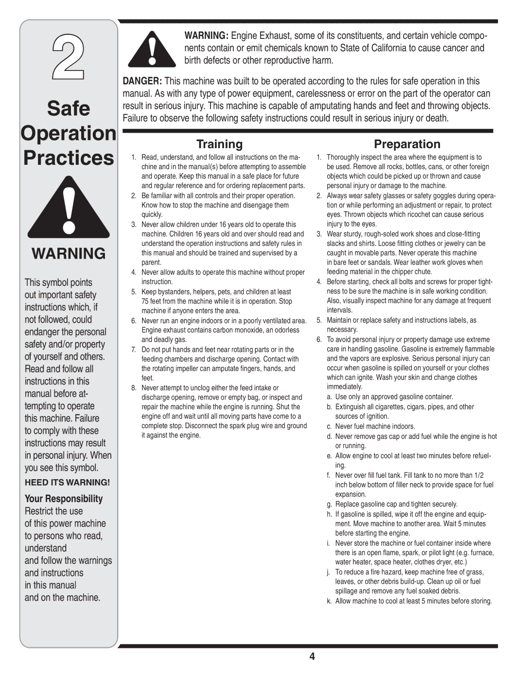
Parts List
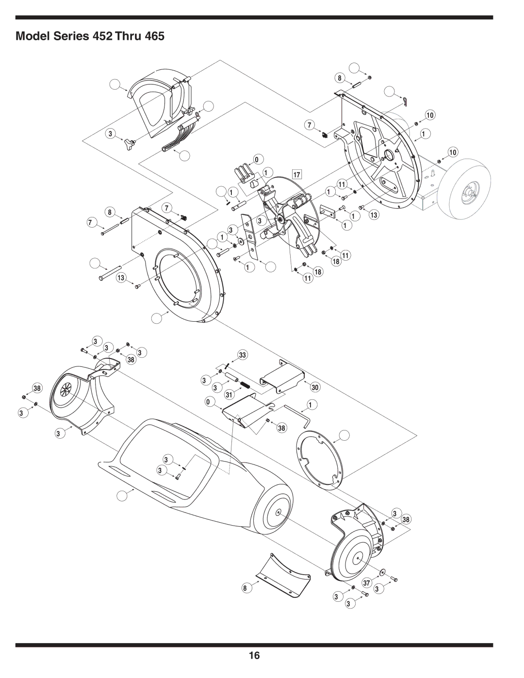
To order replacement parts, contact
NOTE: This Operators Manual covers a range of product specifica- tions for various models. Characteristics and features discussed and/or illustrated in this manual may not be ap- plicable to all models. MTD LLC reserves the right to change product specifications, designs and equipment without notice and without incurring obligation.
17
