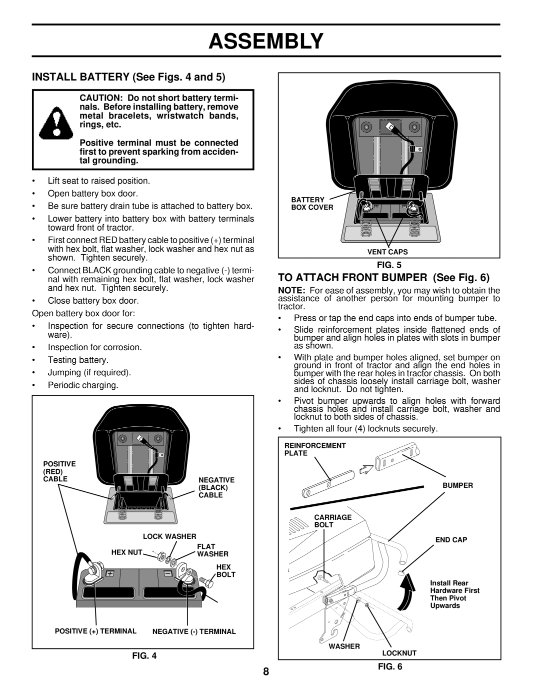
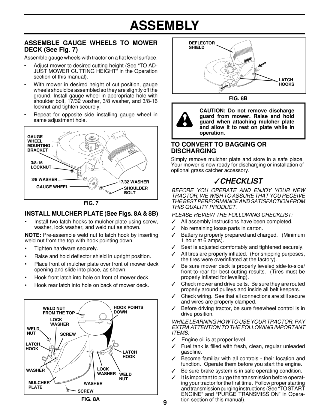
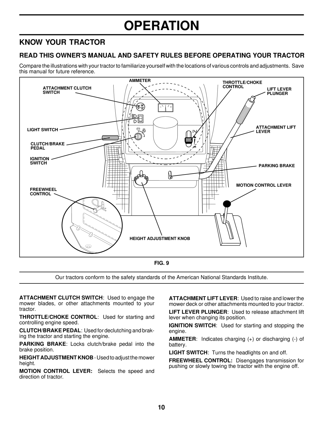
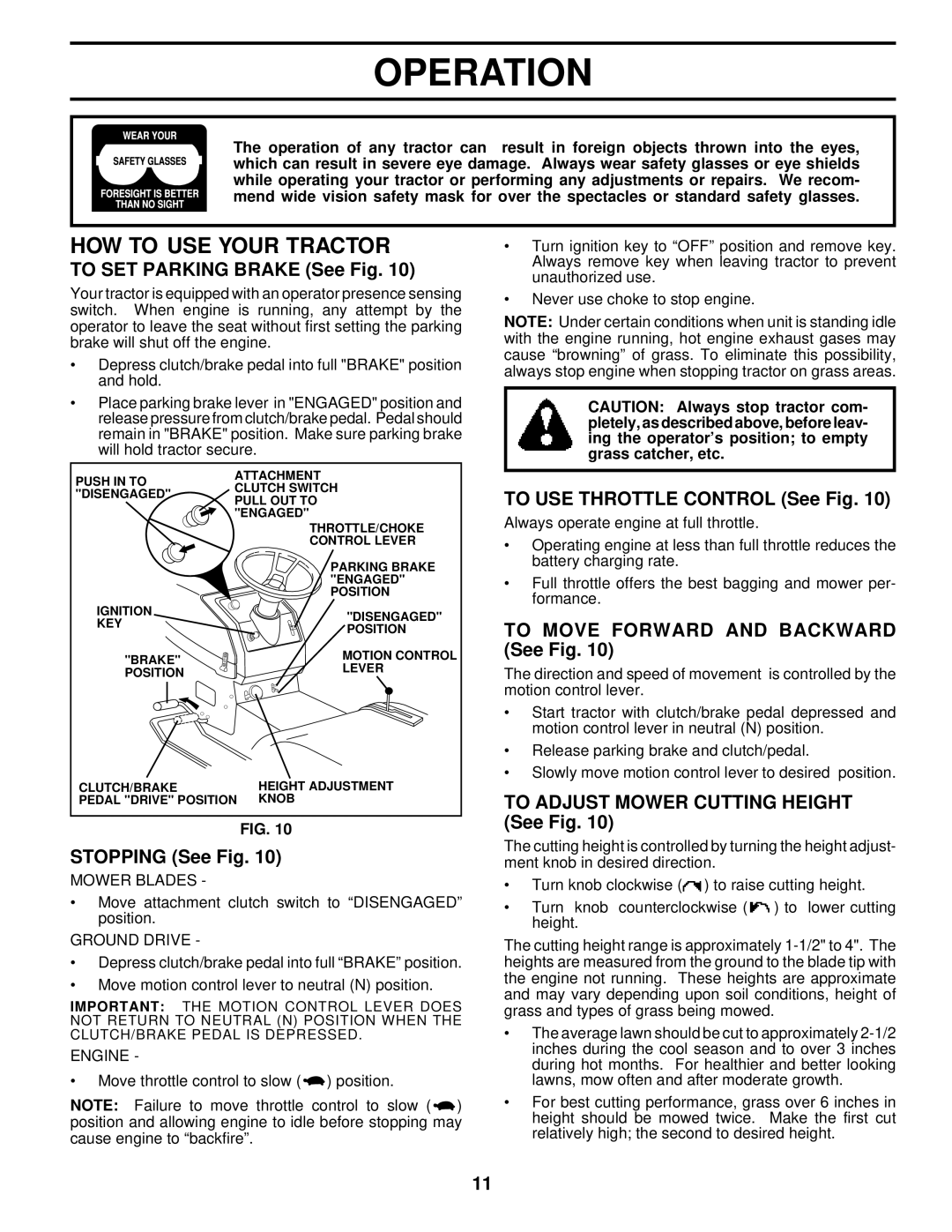
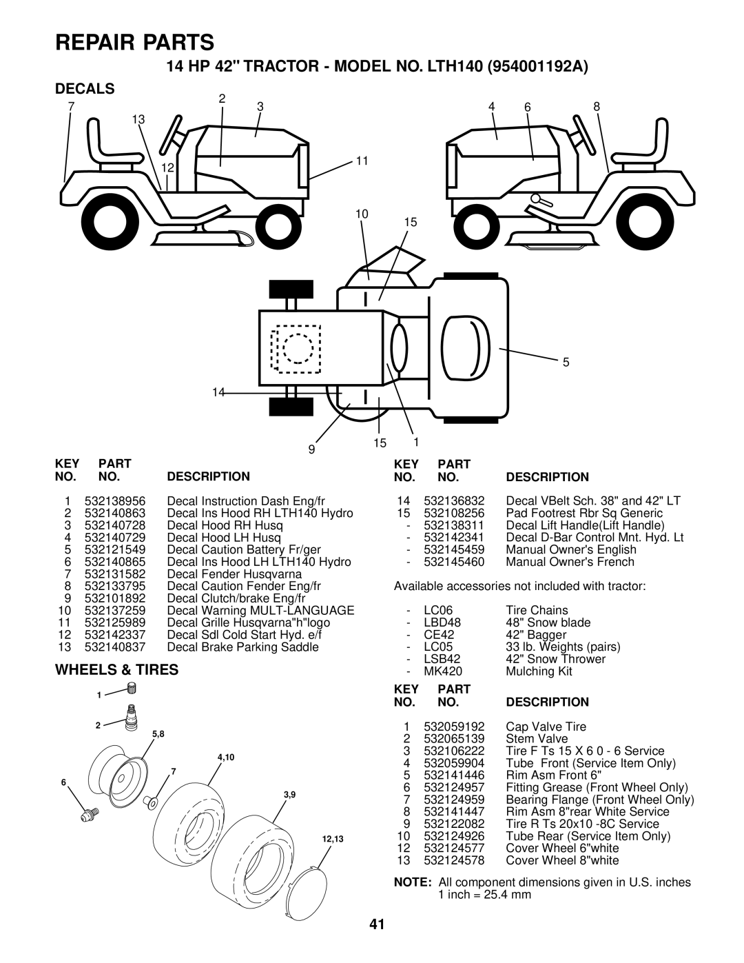
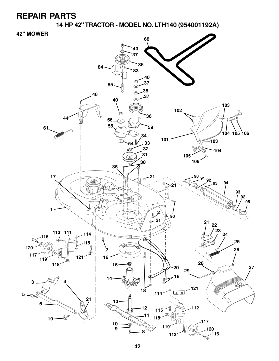
Husqvarna LTH140 Service and Adjustments, To Remove Mower See Fig, To Install Mower See Fig

Page 19

SERVICE AND ADJUSTMENTS

CAUTION: BEFORE PERFORMING ANY SERVICE OR ADJUSTMENTS:

Depress clutch/brake pedal fully and set parking brake.

Place motion control lever in neutral (N) position.

Place attachment clutch in "DISENGAGED" position.

Turn ignition key "OFF" and remove key.

Make sure the blades and all moving parts have completely stopped.

Disconnect spark plug wire from spark plug and place wire where it cannot come in contact with plug.

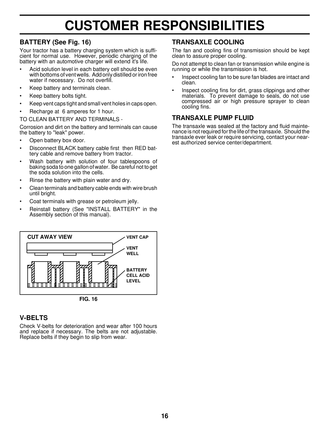
TO REMOVE MOWER (See Fig. 20)

Mower will be easier to remove from the right side of tractor.

Place attachment clutch switch in “DISENGAGED” position.

Move attachment lift lever forward to lower mower to its lowest position.

Roll belt off electric clutch pulley.

Disconnect anti-sway bar from chassis bracket by removing retainer spring.

Disconnect suspension arms from rear deck brackets by removing retainer springs.

Disconnect front links from deck by removing retainer springs.

Raise lift lever to raise suspension arms. Slide mower out from under tractor.

IMPORTANT: IF AN ATTACHMENT OTHER THAN THE MOWER IS TO BE MOUNTED TO THE TRACTOR, THE R.H. AND L.H. SUSPENSION ARMS MUST BE REMOVED FROM TRACTOR.

SUSPENSION

ELECTRIC

ARMS


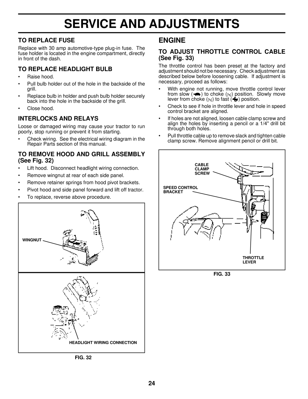
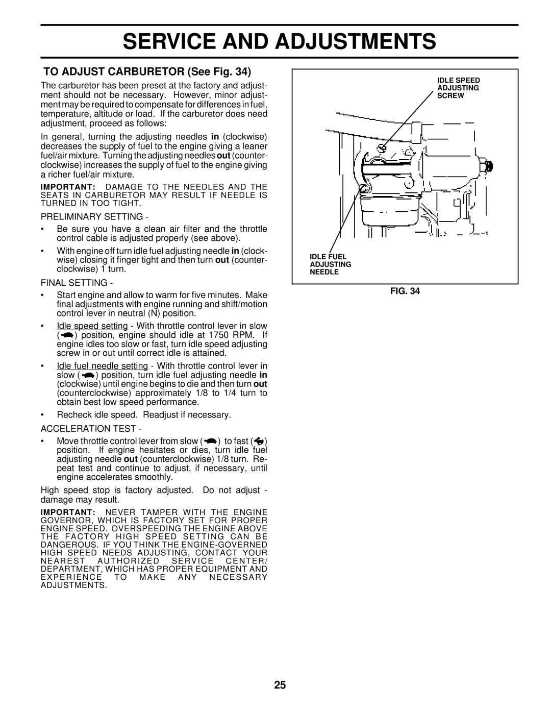
CLUTCH


PULLEY


RETAINER


SPRINGS


(BOTH SIDES)

RETAINER


SPRING


ANTI-SWAY BAR

RETAINER


SPRINGS


(BOTH SIDES)

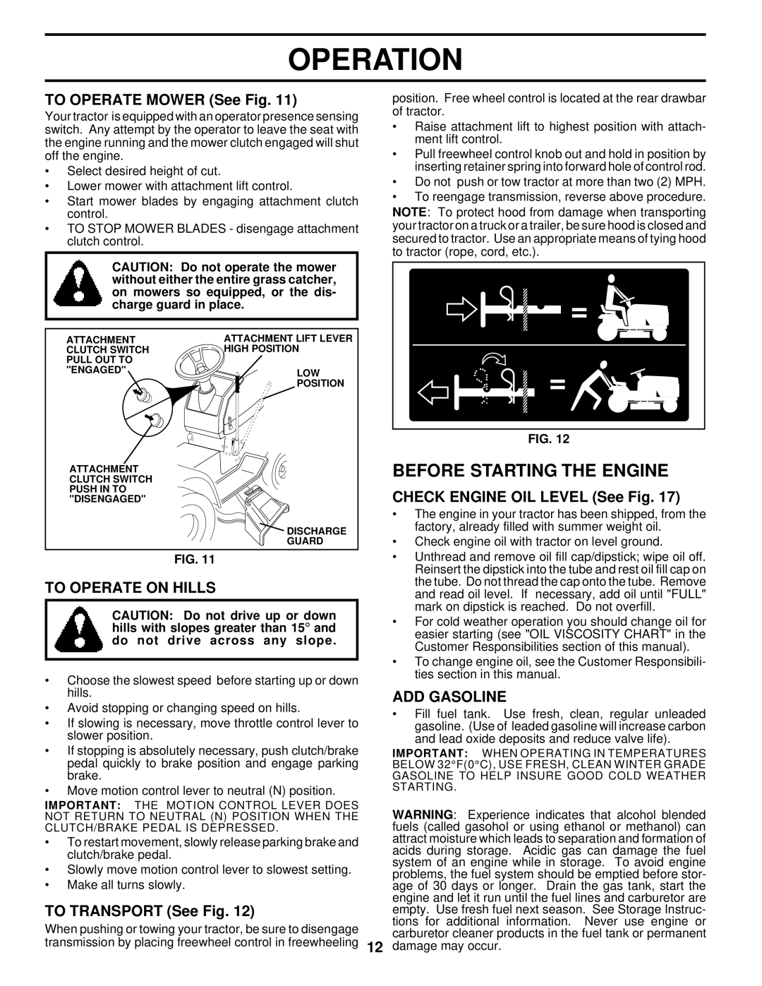
FIG. 20

TO INSTALL MOWER (See Fig. 20)

Raise attachment lift lever to its highest position.

Slide mower under tractor with discharge guard to right side of tractor.

Lower lift lever to its lowest position.

Install mower in reverse order of removal instructions.

19
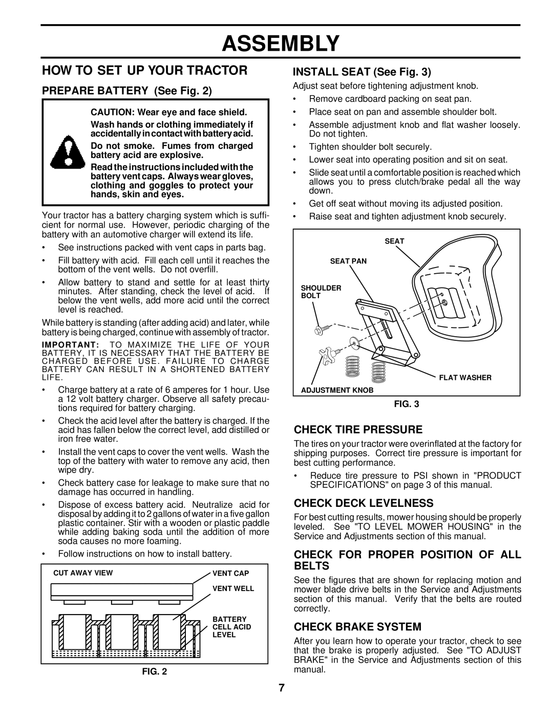
Image 19
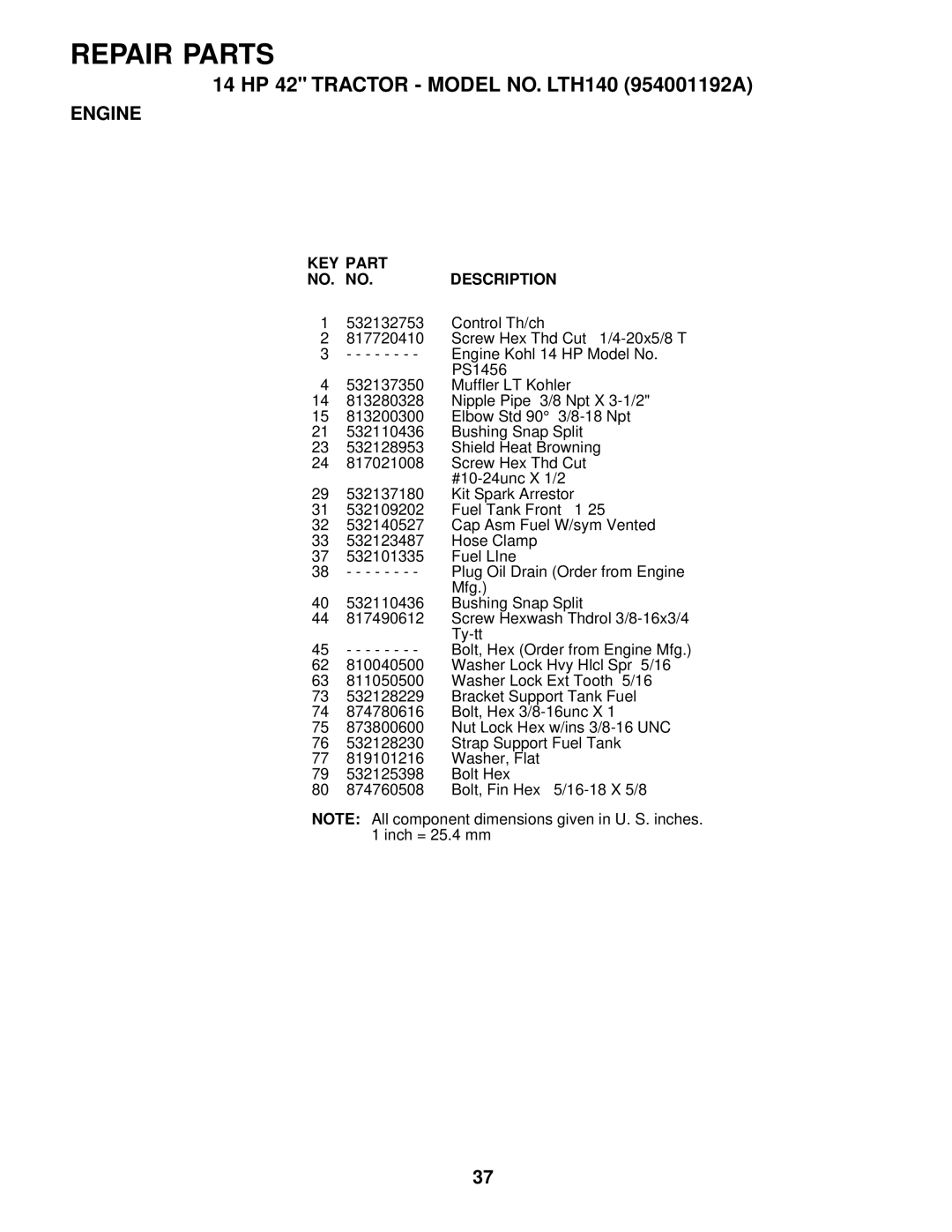
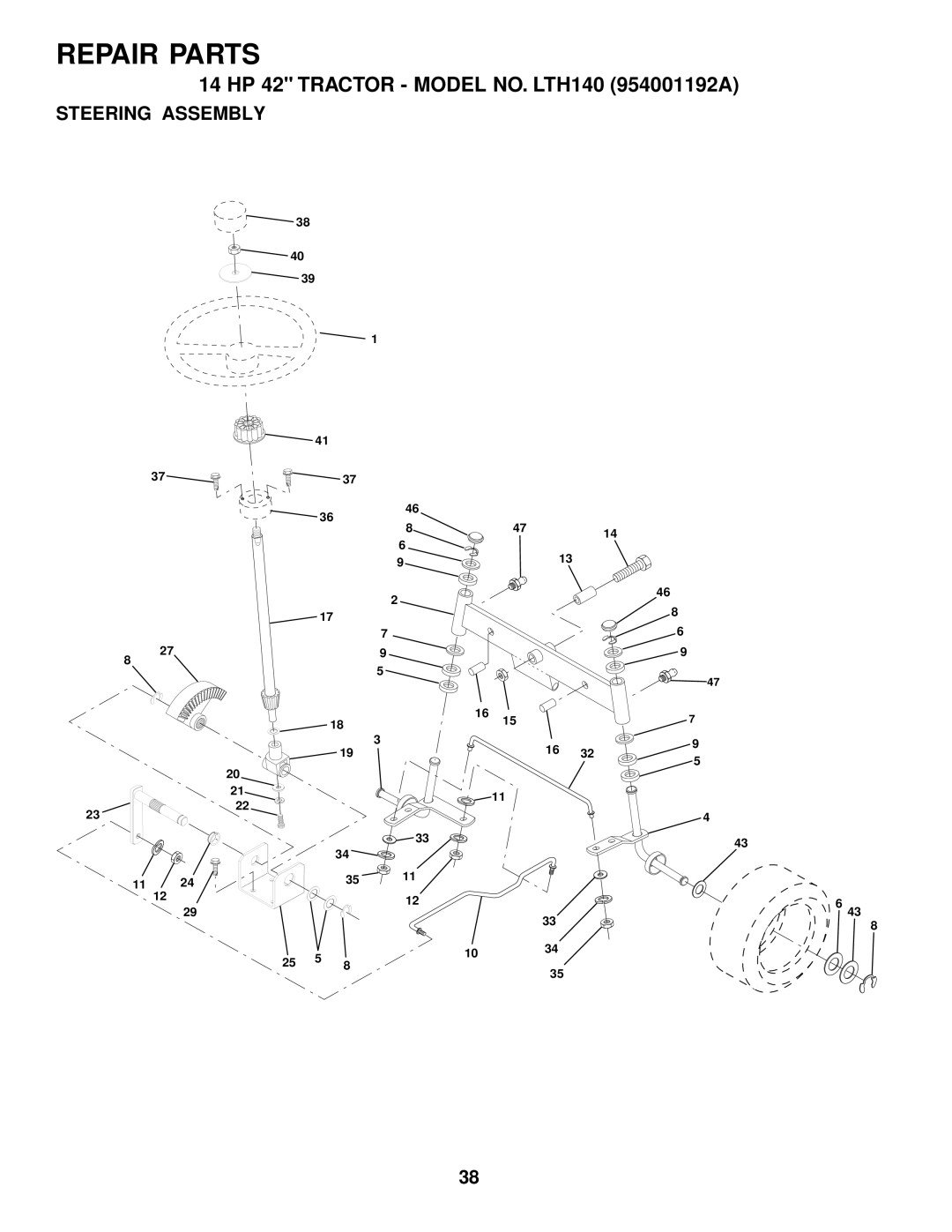
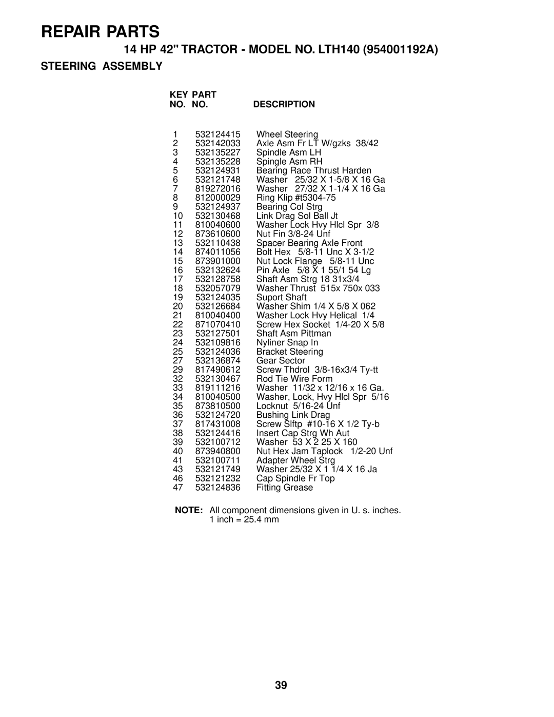
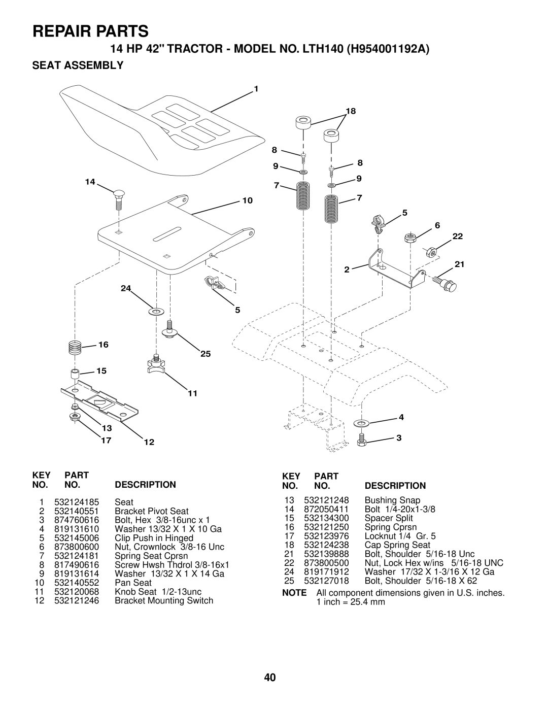
Contents LT H 1 4 Safe Operation Practices for Ride-On Mowers Safety RulesCustomer Responsibilities Product SpecificationsModel Number LTH140 Serial Table of Contents Contents of Hardware Pack Before Rolling Tractor OFF Skid AssemblyTools Required for Assembly To Remove Tractor from CartonCheck for Proper Position of ALL Belts HOW to SET UP Your TractorCheck Tire Pressure Check Deck LevelnessTo Attach Front Bumper See Fig Install Battery See FigsTo Convert to Bagging or Discharging Assemble Gauge Wheels to Mower Deck See FigKnow Your Tractor OperationHOW to USE Your Tractor To Operate on Hills Before Starting the EngineADD Gasoline To Start Engine See Fig Mowing TipsPurge Transmission General Recommendations Lubrication ChartService Dates Customer ResponsibilitiesBlade Care TractorBrake Operation TiresTransaxle Cooling Battery See FigTo Clean Battery and Terminals BeltsLubrication To Service PRE-CLEANERTo Service Cartridge EngineSpark Plugs CleaningClean AIR INTAKE/COOLING Areas MufflerTo Install Mower See Fig Service and AdjustmentsTo Remove Mower See Fig FRONT-TO-BACK Adjustment See Figs To Level Mower HousingTo Replace Mower Blade Drive Belt See Fig To Adjust Attachment Clutch See FigTo Adjust Brake See Fig Belt InstallationTransmission REMOVAL/REPLACEMENT To Adjust Motion Control Lever See FigTo Replace Motion Drive Belt See Fig To Remove Wheel for Repairs See Fig To Adjust Steering Wheel AlignmentTo Start Engine with a Weak Battery See Fig Front Wheel TOE-IN/CAMBERTo Replace Headlight Bulb To Remove Hood and Grill Assembly See FigTo Adjust Throttle Control Cable See Fig To Replace FuseAcceleration Test To Adjust Carburetor See FigPreliminary Setting Final SettingOther StorageProblem Cause Correction Troubleshooting PointsOFF 14 HP 42 Tractor Model NO. LTH140 954001192A SchematicElectrical KEY Part NO. NO. Description Chassis and Enclosures KEY Part NO. no Description Drive KEY Part Description Engine 532132753 Control Th/ch Steering Assembly Repair Parts 14 HP 42 Tractor Model NO. LTH140 H954001192A Seat AssemblyLBD48 DecalsLSB42 Mower KEY Part NO. no Description Mower Lift Assembly Repair Parts HYDRO-GEAR Transaxle Model no Repair Parts Service Notes Service Notes Sighting Guide Suggested Guide for Sighting Slopes for Safe OperationLimited Warranty Warranty Statement