100 TX specifications
The 3Com 100 TX is a leading networking device that revolutionized Ethernet connectivity in both small and large enterprise environments. As a part of the 3Com family, this device was designed to provide reliable and efficient network performance, supporting the growing demands of networking technologies in the late 1990s and early 2000s.One of the main features of the 3Com 100 TX is its compliance with the 100BASE-TX standard, enabling rapid data rates of up to 100 Mbps. This makes it ideal for high-speed local area networks (LANs) that require swift data transfer among connected devices. The device effectively accommodates the increasing bandwidth needs brought on by resource-heavy applications and the proliferation of internet services.
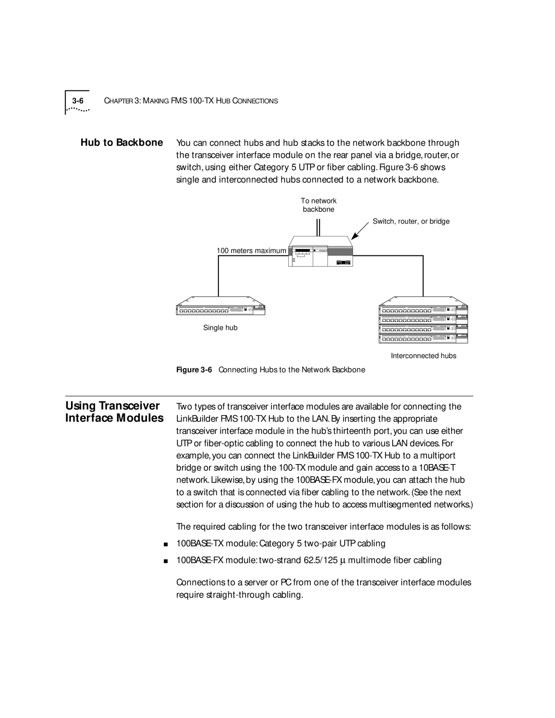
The 3Com 100 TX employs a Category 5 cabling system, which is crucial in achieving optimal performance. This cabling type allows for improved signal quality and reduced crosstalk, particularly over longer distances. By integrating this technology, the 3Com 100 TX can maintain a reliable point-to-point connection, ensuring minimal packet loss and superior data integrity.
Another significant characteristic of the 3Com 100 TX is its innovative design, which facilitates easy installation and integration into existing network infrastructures. The device features auto-negotiation capabilities, allowing it to automatically detect and adapt to the speed and duplex settings of connected devices. This plug-and-play functionality minimizes configuration time, making it user-friendly for both seasoned network engineers and those new to networking.
In terms of network management, 3Com incorporated various tools to help administrators monitor and troubleshoot network performance efficiently. The device includes diagnostic indicators such as Link and Activity LEDs, providing real-time feedback on connection statuses. This aids in quick identification of potential issues or downtime, ensuring network reliability.
Overall, the 3Com 100 TX remains a noteworthy component in the evolution of Ethernet technology. Its exceptional speed, flexible cabling compatibility, and user-oriented design make it an enduring choice for businesses seeking to enhance their network infrastructure. By investing in such devices, organizations can achieve optimal connectivity, laying a strong foundation for a robust digital ecosystem.

