SuperStack® 3 Switch 4300
DUA1712-1AAA01
S/N: | XXXX/7XXXXXXXXX |
|
3C17121 | SuperStack |
|
|
|
|
|
|
| |
| 3 | Switch |
|
|
|
| 4300 | 1000BASE- | |
|
|
| ||
|
|
|
| |
|
|
|
| T |
![]() 10
10
100 1000
‘roll
INTRODUCTION
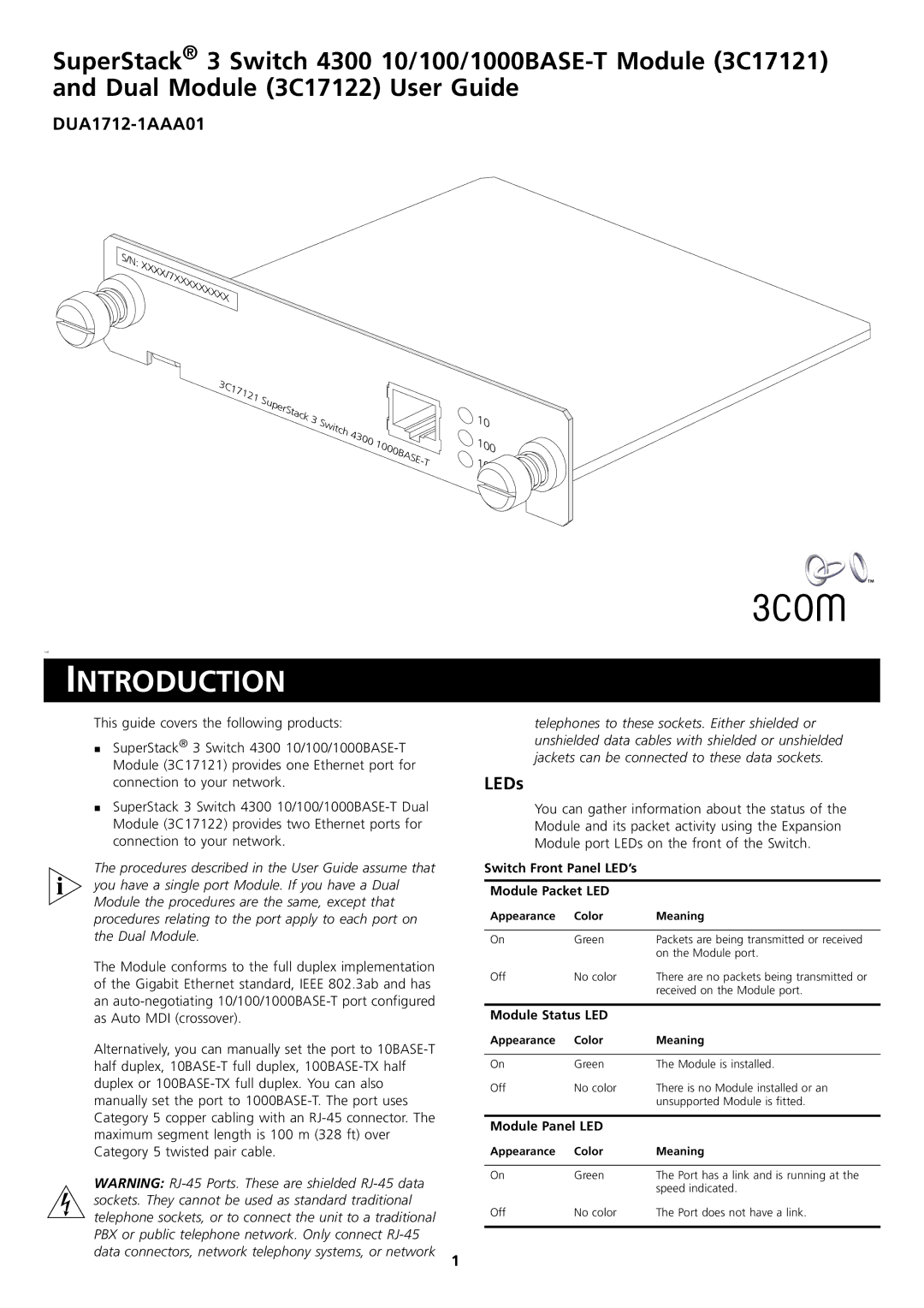
his guide covers the following products:
SuperStack® 3 Switch 4300
SuperStack 3 Switch 4300
The procedures described in the User Guide assume that you have a single port Module. If you have a Dual Module the procedures are the same, except that procedures relating to the port apply to each port on the Dual Module.
telephones to these sockets. Either shielded or unshielded data cables with shielded or unshielded jackets can be connected to these data sockets.
LEDs
You can gather information about the status of the Module and its packet activity using the Expansion Module port LEDs on the front of the Switch.
Switch Front Panel LED’s
Module Packet LED
Appearance | Color | Meaning |
|
|
|
On | Green | Packets are being transmitted or received |
|
| on the Module port. |
The Module conforms to the full duplex implementation of the Gigabit Ethernet standard, IEEE 802.3ab and has an
Alternatively, you can manually set the port to
WARNING:
1
Off | No color | There are no packets being transmitted or |
|
| received on the Module port. |
|
| |
Module Status LED |
| |
Appearance | Color | Meaning |
|
|
|
On | Green | The Module is installed. |
Off | No color | There is no Module installed or an |
|
| unsupported Module is fitted. |
|
| |
Module Panel LED |
| |
Appearance | Color | Meaning |
|
|
|
On | Green | The Port has a link and is running at the |
|
| speed indicated. |
Off | No color | The Port does not have a link. |
|
|
|
