User Manual |
|
| |
Power System | Chapter 2 System Description |
Chapter 2 System Description
2.1 Overview
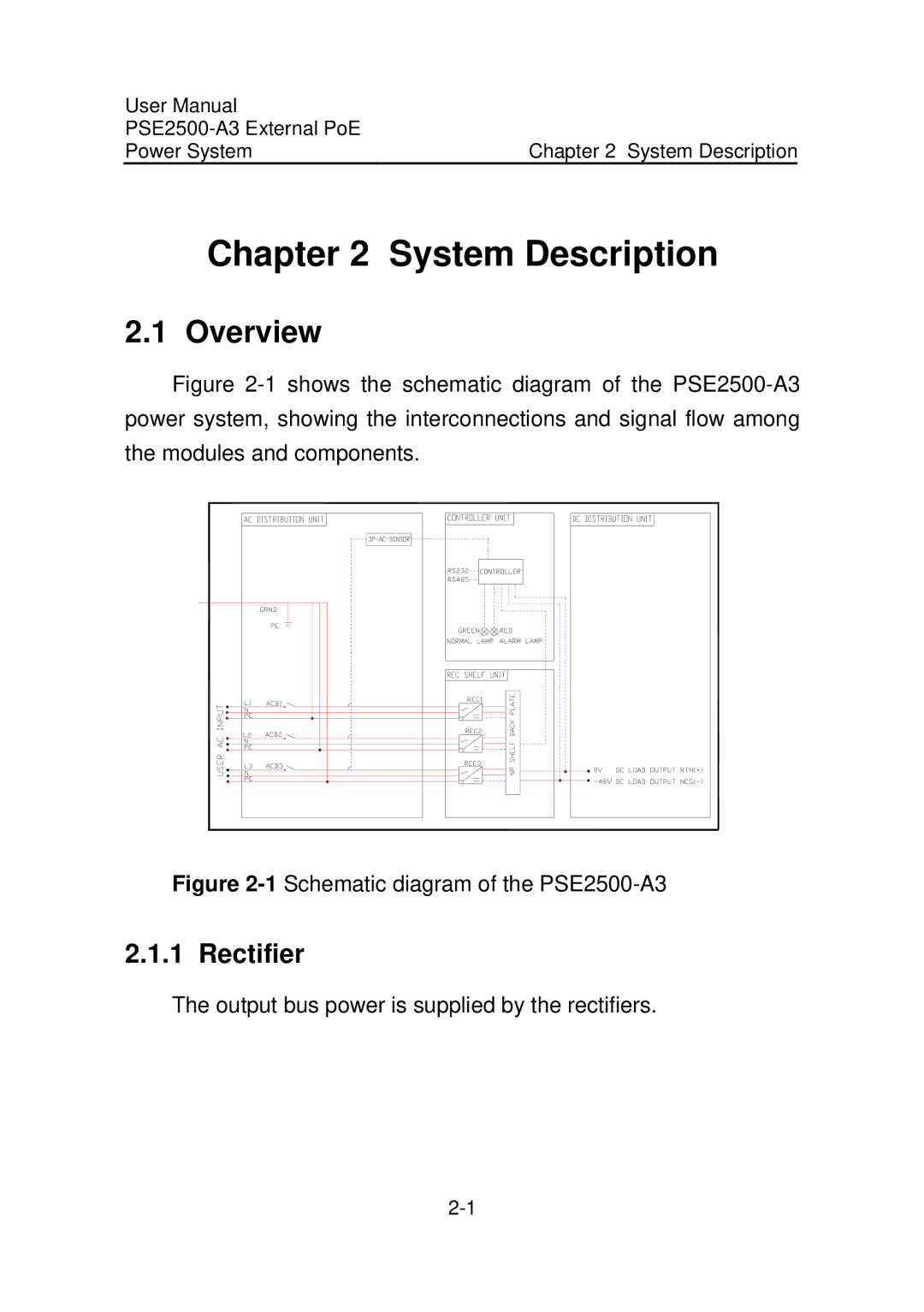
Figure 2-1 shows the schematic diagram of the PSE2500-A3 power system, showing the interconnections and signal flow among the modules and components.
Figure 2-1 Schematic diagram of the PSE2500-A3
2.1.1 Rectifier
The output bus power is supplied by the rectifiers.