UNCONFINED SPACE
In buildings of conventional frame, brick or stone construction, unconfined spaces may provide adequate air for combustion, ventilation, and draft hood dilution.
If the unconfined space is within a building of tight construction (building using the following construction: weather stripping, heavy insulation, caulking, vapor barrier, etc.), air for combustion, ventilation, and draft hood dilution must be obtained from outdoors. The installation instructions for confined spaces must be followed.
CONFINED SPACE
When drawing combustion and dilution air from inside a conventionally constructed building to a confined space, such a space shall be provided with two permanent openings. ONE IN OR WITHIN 12 INCHES OF THE ENCLOSURE TOP AND ONE IN OR WITHIN 12 INCHES OF THE ENCLOSURE BOTTOM. Each opening shall have a free area of at least one square inch per 1000 Btuh of the total input of all appliances in the enclosure, but not less than 100 square inches.
If the confined space is within a building of tight construction, air for combustion, ventilation and draft hood dilution must be obtained from outdoors. When directly communicating with the outdoors or communicating through vertical ducts, two permanent openings, located in the above manner, shall be provided. Each opening shall have a free area of not less than one square inch per 4000 Btuh of the total input of all appliances in the enclosure. If horizontal ducts are used, each opening shall have a free area of not less than one square inch per 2000 Btuh of the total input of all appliances in the enclosure.
In calculating the free area of a vent opening, the blocking effect of screens, louvers and grills should be considered. Screens shall not be of a mesh smaller than 1/4 inch square. If the free area is not known, the latest edition of National Fuel Gas Code ANSI Z223.1 recommends using figures of 20-25 percent free area for wood louvers or 60-75 percent for metal grills or louvers.
WATER CONNECTIONS
Refer to figure 1 for typical installation. A suitable pipe thread sealant must be used to prevent leakage.
WATER (POTABLE) HEATING AND SPACE HEATING
For WATER HEATING (POTABLE) and SPACE HEATING:
1.All piping components connected to this unit for space heating applications shall be suitable for use with potable water.
2.Toxic chemicals, such as those used for boiler treatment, shall NEVER be introduced into this system.
3.This unit may NEVER be connected to any existing heating system or component(s) previously used with a non-potable water heating appliance.
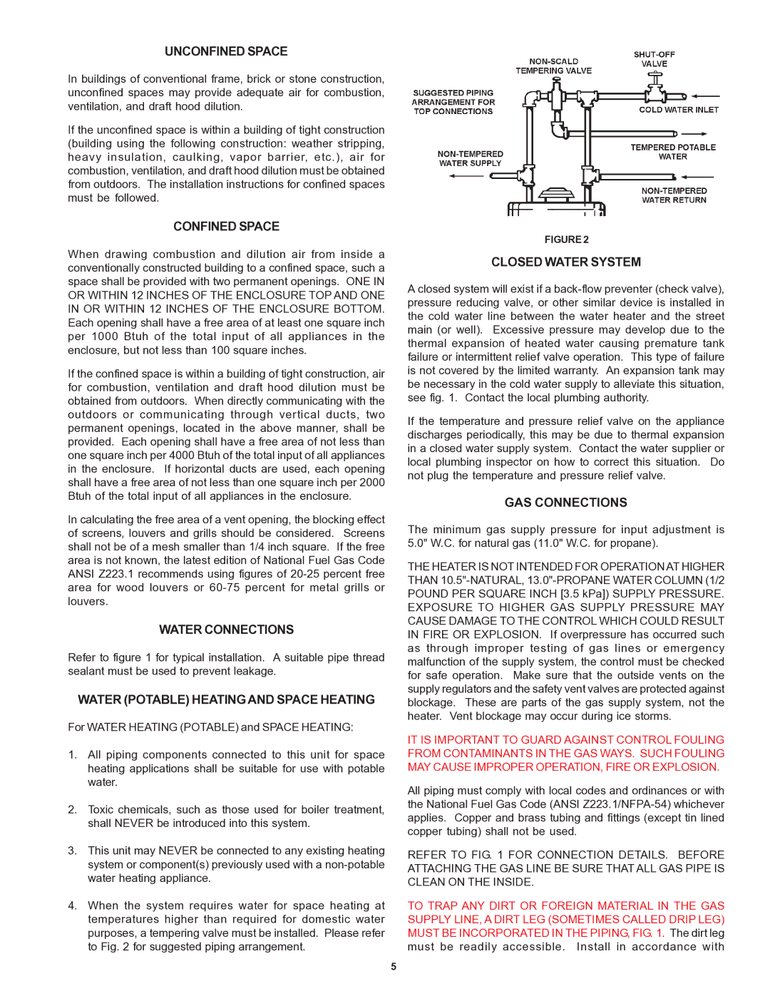
4.When the system requires water for space heating at temperatures higher than required for domestic water purposes, a tempering valve must be installed. Please refer to Fig. 2 for suggested piping arrangement.
FIGURE 2
CLOSED WATER SYSTEM
A closed system will exist if a back-flow preventer (check valve), pressure reducing valve, or other similar device is installed in the cold water line between the water heater and the street main (or well). Excessive pressure may develop due to the thermal expansion of heated water causing premature tank failure or intermittent relief valve operation. This type of failure is not covered by the limited warranty. An expansion tank may be necessary in the cold water supply to alleviate this situation, see fig. 1. Contact the local plumbing authority.
If the temperature and pressure relief valve on the appliance discharges periodically, this may be due to thermal expansion in a closed water supply system. Contact the water supplier or local plumbing inspector on how to correct this situation. Do not plug the temperature and pressure relief valve.
GAS CONNECTIONS
The minimum gas supply pressure for input adjustment is 5.0" W.C. for natural gas (11.0" W.C. for propane).
THE HEATER IS NOT INTENDED FOR OPERATION AT HIGHER THAN 10.5"-NATURAL, 13.0"-PROPANE WATER COLUMN (1/2 POUND PER SQUARE INCH [3.5 kPa]) SUPPLY PRESSURE. EXPOSURE TO HIGHER GAS SUPPLY PRESSURE MAY CAUSE DAMAGE TO THE CONTROL WHICH COULD RESULT IN FIRE OR EXPLOSION. If overpressure has occurred such as through improper testing of gas lines or emergency malfunction of the supply system, the control must be checked for safe operation. Make sure that the outside vents on the supply regulators and the safety vent valves are protected against blockage. These are parts of the gas supply system, not the heater. Vent blockage may occur during ice storms.
IT IS IMPORTANT TO GUARD AGAINST CONTROL FOULING FROM CONTAMINANTS IN THE GAS WAYS. SUCH FOULING MAY CAUSE IMPROPER OPERATION, FIRE OR EXPLOSION.
All piping must comply with local codes and ordinances or with the National Fuel Gas Code (ANSI Z223.1/NFPA-54) whichever applies. Copper and brass tubing and fittings (except tin lined copper tubing) shall not be used.
REFER TO FIG. 1 FOR CONNECTION DETAILS. BEFORE ATTACHING THE GAS LINE BE SURE THAT ALL GAS PIPE IS CLEAN ON THE INSIDE.
TO TRAP ANY DIRT OR FOREIGN MATERIAL IN THE GAS SUPPLY LINE, A DIRT LEG (SOMETIMES CALLED DRIP LEG) MUST BE INCORPORATED IN THE PIPING, FIG. 1. The dirt leg must be readily accessible. Install in accordance with