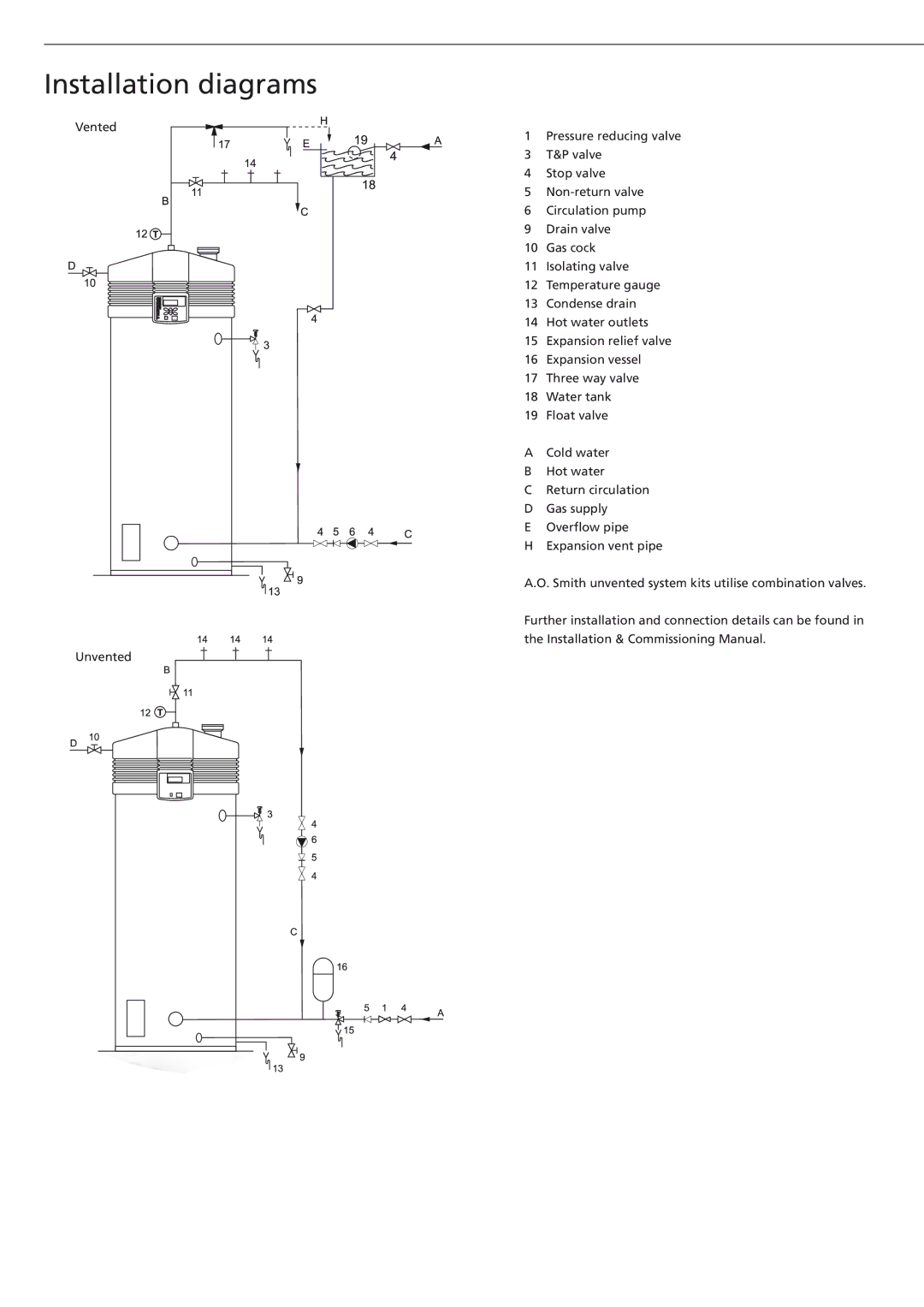
BFC - 100, BFC - 50, BFC - 28 specifications
A.O. Smith is a leading manufacturer in the water heating industry, known for its innovative technologies and high-quality products. Among their impressive line of offerings, the BFC series stands out with three models: the BFC - 28, BFC - 50, and BFC - 100. Each model is designed to meet various heating needs while providing efficiency and reliability.The A.O. Smith BFC - 28 is an ideal choice for small to medium-sized homes or commercial applications, delivering a maximum output of 28 kW. This model is equipped with advanced heating technology, enabling rapid water heating without significant energy loss. Its compact design is perfect for installations where space is limited, while still providing consistent performance. Key features include a digital thermostat for precise temperature control and an automated system that optimizes energy consumption, leading to cost savings on utility bills.
The BFC - 50 model steps up the performance for larger households, offering 50 kW of heating power. This model is engineered for high-demand scenarios, making it suitable for properties with multiple bathrooms or heavy usage. Similar to the BFC - 28, it incorporates a user-friendly digital interface for effortless temperature adjustments. Its tankless design ensures an endless supply of hot water, while built-in safety features protect against overheating and energy waste.
For those requiring maximum capacity, the BFC - 100 shines with a robust 100 kW output. This model is perfect for large commercial applications or sprawling residences, providing a continuous flow of hot water to meet the highest demands. The BFC - 100 is designed with cutting-edge insulation technology, which minimizes heat loss and enhances energy efficiency. It also features smart connectivity options, allowing users to monitor and control hot water supply remotely.
All three models benefit from A.O. Smith's commitment to sustainability. They are designed with energy-efficient components that meet stringent environmental regulations. Furthermore, their user-friendly maintenance features make it easy for technicians to perform service, ensuring long-lasting performance.
In summary, A.O. Smith's BFC - 28, BFC - 50, and BFC - 100 models deliver exceptional performance, advanced technology, and energy efficiency, making them ideal solutions for various hot water demands. Whether for residential or commercial use, these heaters represent the pinnacle of modern water heating technology, keeping homes and businesses running smoothly.

