A.O. Smith BFC - 50, BFC - 100, BFC - 28 manual Installation options, Minimum space requirements

Models: BFC - 100 BFC - 50 BFC - 28

1 6
Download 6 pages 22.5 Kb
Page 6
Image 6

Flue systems Cyclone BFC

Installation options

C13

B23

C33

C53

C43

Flue systems Cyclone BFC

Minimum space requirements

BFC 28-60

BFC 80-100

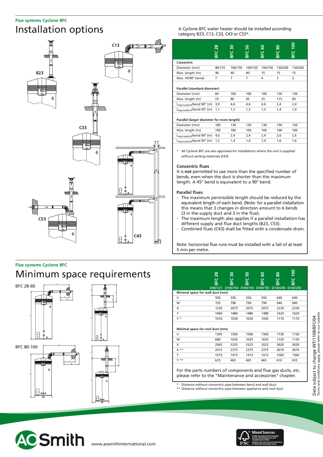
A Cyclone BFC water heater should be installed according category B23, C13, C33, C43 or C53*.


BFC 28

BFC 30

BFC 50

BFC 60

BFC 80

BFC 100

Concentric


Diameter (mm)

80/125

100/150

100/150

100/150

130/200

130/200


Max. length (m)

40

40

40

15

15

15


Max. 45/90° bends

7

7

7

4

3

3


Parallel (standard diameter)


Diameter (mm)

80

100

100

100

130

130


Max. length (m)

25

80

45

25

115

60


Lequivalent/bend 90° (m)

3,9

4,6

4,6

4,6

2,4

2,4

Lequivalent/bend 45º (m)

1,1

1,2

1,2

1,2

1,4

1,4

Parallel (larger diameter for more length)


Diameter (mm)

100

130

130

130

150

150


Max. length (m)

100

100

100

100

100

100


Lequivalent/bend 90º (m)

4,6

2,4

2,4

2,4

2,6

2,6

Lequivalent/bend 45º (m)

1,2

1,4

1,4

1,4

1,6

1,6

*All Cyclone BFC are also approved for installations where the unit is supplied without venting materials (C63).

Concentric flues

It is not permitted to use more than the specified number of bends, even when the duct is shorter than the maximum length. A 45° bend is equivalent to a 90° bend.

Parallel flues

-The maximum permissible length should be reduced by the equivalent length of each bend. (Note: for a parallel installation this means that 3 changes in direction amount to 6 bends (3 in the supply duct and 3 in the flue).

-The maximum length also applies if a parallel installation has different supply and flue duct lengths (B23, C53).

-Combined flues (C43) shall be fitted with a condensate drain.

Note: horizontal flue runs must be installed with a fall of at least 5 mm per metre.


BFC 28

BFC 30

BFC 50

BFC 60

BFC 80

BFC 100


Ø80/125

Ø100/150

Ø100/150

Ø100/150

Ø130/200

Ø130/200


Minimal space for wall duct (mm)


V

550

550

550

550

640

640


W

725

790

790

790

940

940


X

1535

2075

2075

2075

2230

2230


pleaseapply,conditionsand refer to our website

Y

1460

1480

1480

1480

1620

1620

changetosubjectINT/1108/BFC/04


* Distance without concentric pipe between bend and wall duct.


Y *

1010

1030

1030

1030

1170

1170


Minimal space for roof duct (mm)


V

1305

1500

1500

1500

1730

1730


W

680

1035

1035

1035

1120

1120


X

2965

3325

3325

3325

3620

3620


X **

2015

2375

2375

2375

2670

2670


Y

1575

1415

1415

1415

1560

1560


Y **

625

465

465

465

610

610


For the parts numbers of components and flue gas ducts, etc.


please refer to the “Maintenance and accessories” chapter.


Data Terms

** Distance without concentric pipe between appliance and roof duct.


www.aosmithinternational.com

Page 6
Image 6
A.O. Smith BFC - 50, BFC - 100, BFC - 28 manual Installation options, Minimum space requirements

BFC - 100, BFC - 50, BFC - 28 specifications

A.O. Smith is a leading manufacturer in the water heating industry, known for its innovative technologies and high-quality products. Among their impressive line of offerings, the BFC series stands out with three models: the BFC - 28, BFC - 50, and BFC - 100. Each model is designed to meet various heating needs while providing efficiency and reliability.

The A.O. Smith BFC - 28 is an ideal choice for small to medium-sized homes or commercial applications, delivering a maximum output of 28 kW. This model is equipped with advanced heating technology, enabling rapid water heating without significant energy loss. Its compact design is perfect for installations where space is limited, while still providing consistent performance. Key features include a digital thermostat for precise temperature control and an automated system that optimizes energy consumption, leading to cost savings on utility bills.

The BFC - 50 model steps up the performance for larger households, offering 50 kW of heating power. This model is engineered for high-demand scenarios, making it suitable for properties with multiple bathrooms or heavy usage. Similar to the BFC - 28, it incorporates a user-friendly digital interface for effortless temperature adjustments. Its tankless design ensures an endless supply of hot water, while built-in safety features protect against overheating and energy waste.

For those requiring maximum capacity, the BFC - 100 shines with a robust 100 kW output. This model is perfect for large commercial applications or sprawling residences, providing a continuous flow of hot water to meet the highest demands. The BFC - 100 is designed with cutting-edge insulation technology, which minimizes heat loss and enhances energy efficiency. It also features smart connectivity options, allowing users to monitor and control hot water supply remotely.

All three models benefit from A.O. Smith's commitment to sustainability. They are designed with energy-efficient components that meet stringent environmental regulations. Furthermore, their user-friendly maintenance features make it easy for technicians to perform service, ensuring long-lasting performance.

In summary, A.O. Smith's BFC - 28, BFC - 50, and BFC - 100 models deliver exceptional performance, advanced technology, and energy efficiency, making them ideal solutions for various hot water demands. Whether for residential or commercial use, these heaters represent the pinnacle of modern water heating technology, keeping homes and businesses running smoothly.