Cyclone BFC
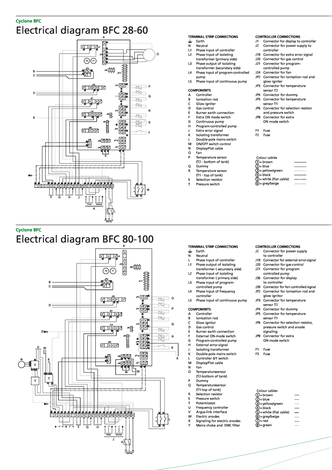
Electrical diagram BFC 28-60
TERMINAL STRIP CONNECTIONS | CONTROLLER CONNECTIONS | ||||||||
|
| Earth | J1 | Connector for display to controller | |||||
|
| ||||||||
N | Neutral | J2 | Connector for power supply to | ||||||
L1 | Phase input of controller |
| controller | ||||||
L2 | Phase input of isolating | J19 | Connector for extra error signal | ||||||
|
| transformer (primary side) | J20 | Connector for gas control | |||||
L3 | Phase output of isolating | J21 | Connector for program- | ||||||
|
| transformer (secondary side) |
| controlled pump | |||||
L4 | Phase input of | J24 | Connector for fan | ||||||
|
| pump | JP2 | Connector for ionisation rod and | |||||
L5 | Phase input of continuous pump |
| glow igniter | ||||||
|
|
| JP3 | Connector for temperature | |||||
COMPONENTS |
| sensor T2 | |||||||
A | Controller | JP4 | Connector for dummy | ||||||
B | Ionisation rod | JP5 | Connector for temperature | ||||||
C | Glow igniter |
| sensor T1 | ||||||
D | Gas control | JP6 | Connector for selection resistor | ||||||
E | Burner earth connection |
| and pressure switch | ||||||
F | Extra ON mode switch | JP8 | Connector for extra | ||||||
G | Continuous pump |
| ON mode switch | ||||||
H |
|
|
|
|
|
|
| ||
J | Extra error signal | F1 | Fuse | ||||||
K | Isolating transformer | F2 | Fuse | ||||||
L |
|
|
|
|
|
|
| ||
M | ON/OFF switch control |
|
|
|
|
|
|
| |
N | Display/Flat cable |
|
|
|
|
|
|
| |
O | Fan |
|
|
|
|
|
|
| |
P | Temperature sensor | Colour cables | |||||||
|
| (T2 - bottom of tank) | 1 = brown |
|
| ||||
|
|
| |||||||
Q | Dummy | 2 = blue |
|
| |||||
| |||||||||
R | Temperature sensor | 3 = yellow/green |
|
| |||||
| |||||||||
|
| (T1 - top of tank) | 4 = black |
|
| ||||
|
|
| |||||||
S | Selection resistor | 5 = white (flat cable) |
|
|
|
| |||
|
| ||||||||
T | Pressure switch | 6 = grey/beige |
|
|
|
|
| ||
|
|
| |||||||
Cyclone BFC
Electrical diagram BFC
TERMINAL STRIP CONNECTIONS
|
| Earth |
N | Neutral | |
L | Phase input of controller | |
L1 | Phase output of isolating | |
|
| transformer ( secundary side) |
L2 | Phase input of isolating | |
|
| transformer ( primary side) |
L3 | Phase input of program- | |
|
| controlled pump |
L4 | Phase input of frequency | |
|
| controller |
L5 | Phase input of continuous pump | |
COMPONENTS | ||
A | Controller | |
B | Ionisation rod | |
C | Glow ignitor | |
D | Gas control | |
E | Burner earth connection | |
F | External | |
G | ||
H | External | |
J | Isolating transformer | |
K | ||
L | Controller 0/1 switch | |
M | Display/Flat cable | |
N | Fan | |
O | Temperaturesensor | |
|
| |
P | Dummy | |
Q | Temperaturesensor | |
|
| |
R | Selection resistor | |
S | Pressure switch | |
T | Potentiostat | |
U | Frequency controller | |
V | ||
W | Electric anodes | |
X | Signaling for electric anodes | |
Y | Mains choke and EMC filter | |
CONTROLLER CONNECTIONS
J2 | Connector for power supply |
| to controller |
J19 | Connector for external |
J20 | Connector for |
J21 | Connector for program |
| controlled pump |
J36 | Connector for display |
| to controller |
J39 | Connector for fan controlled signal |
JP2 | Connector for ionisation rod and |
| glow ignitor |
JP3 | Connector for temperature |
| sensor T2 |
JP4 | Connector for dummy |
JP5 | Connector for temperature |
| sensor T1 |
JP6 | Connector for selection resistor, |
| pressure switch and anode |
| signaling |
JP8 | Connector for extra |
| |
F1 | Fuse |
F3 | Fuse |
Colour cables
1= brown
2= blue
3= yellow/green
4= black
5= white (flat cable)
6= grey/beige
7= red
8= green