2.Drill a pilot hole approximately 1/4" (6 mm) outside of the marked circle. This pilot hole is used as a starting point for a saws-all or sabre saw blade. Cut around the marked circle staying approximately one quarter inch outside the line. (This will allow the vent pipe to easily slide through the opening). The resulting gap will be covered by the roof boot/flashing.

3.Suspend the pipe through center of hole using proper support.

4.Slide roof boot or equivalent flashing over pipe and secure roof boot equivalent flashing to roof.

5.Seal around flashing.

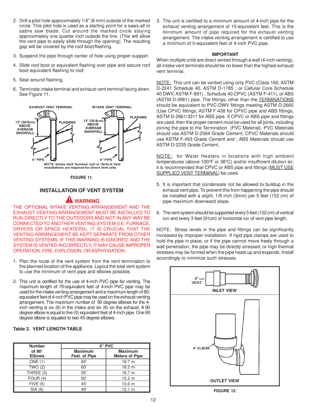
6.Terminate intake terminal and exhaust vent terminal facing down. See Figure 11.

FIGURE 11.

INSTALLATION OF VENT SYSTEM

WARNING

THE OPTIONAL INTAKE VENTING ARRANGEMENT AND THE EXHAUST VENTING ARRANGEMENT MUST BE INSTALLED TO RUN DIRECTLY TO THE OUTDOORS AND NOT IN ANY WAY BE CONNECTED TO ANOTHER VENTING SYSTEM (I.E. FURNACE, DRYERS OR SPACE HEATERS). IT IS CRUCIAL THAT THE VENTING ARRANGEMENT BE KEPT SEPARATE FROM OTHER VENTING SYSTEMS. IF THIS WARNING IS IGNORED, AND THE SYSTEM IS VENTED INCORRECTLY, IT MAY CAUSE IMPROPER OPERATION, FIRE, EXPLOSION, OR ASPHYXIATION.

1.Plan the route of the vent system from the vent termination to the planned location of the appliance. Layout the total vent system to use the minimum of vent pipe and elbows possible.

2.This unit is certified for the use of 4-inch PVC pipe for venting. The maximum length of 70-equivalent feet of 4-inch PVC pipe may be used for the intake venting arrangement and a maximum length of 80- equivalent feet of 4-inch PVC pipe may be used on the exhaust venting arrangement. The maximum number of 90 degree elbows for the 4- inch venting is six (6) in the intake and six (6) on the exhaust. A 90 degree elbow is equal to five (5) equivalent feet of 4-inch pipe. One 90 degree elbow is equaled to two 45 degree elbows.

Table 2. VENT LENGTH TABLE

Number


4" PVC

of 90°

Maximum


Maximum

Elbows

Feet. of Pipe


Meters of Pipe

ONE (1)

65'


19.7 m

TWO (2)

60'


18.2 m

THREE (3)

55'


16.7 m

FOUR (4)

50'


15.2 m

FIVE (5)

45'


13.6 m

SIX (6)

40'


12.1 m

3.The unit is certified to a minimum amount of 4-inch pipe for the exhaust venting arrangement of 15-equivalent feet. This is the minimum amount of pipe required for the exhaust venting arrangement. The intake venting arrangement is certified to use a minimum of 0-equivalent feet of 4-inch PVC pipe.

IMPORTANT

When multiple units are direct vented through a wall (4-inch venting), all intake vent terminals should be no lower than the highest exhaust vent terminal.

NOTE: This unit can be vented using only PVC (Class 160, ASTM D-2241 Schedule 40, ASTM D-1785 ; or Cellular Core Schedule 40 DWV, ASTM F-891) , Schedule 40 CPVC (ASTM F-411), or ABS (ASTM D-2661) pipe. The fittings, other than the TERMINATIONS should be equivalent to PVC-DWV fittings meeting ASTM D-2665 (Use CPVC fittings, ASTM F-438 for CPVC pipe and ABS fittings, ASTM D-2661/3311 for ABS pipe. If CPVC or ABS pipe and fittings are used, then the proper cement must be used for all joints, including joining the pipe to the Termination (PVC Material). PVC Materials should use ASTM D-2564 Grade Cement; CPVC Materials should use ASTM F-493 Grade Cement and ; ABS Materials should use ASTM D-2235 Grade Cement.

NOTE: for Water Heaters in locations with high ambient temperatures (above 100°F or 38°C) and/or insufficient dilution air, it is recommended that CPVC or ABS pipe and fittings (MUST USE SUPPLIED VENT TERMINAL) be used.

5.It is important that condensate not be allowed to buildup in the exhaust vent pipe. To prevent this from happening the pipe should be installed with a slight, 1/8 inch (3mm) per 5 feet (152 cm) of pipe maximum downward slope.

6.The vent system should be supported every 5 feet (152 cm) of vertical run and every 3 feet (91cm) of horizontal run of vent pipe length.

NOTE: Stress levels in the pipe and fittings can be significantly increased by improper installation. If rigid pipe clamps are used to hold the pipe in place, or if the pipe cannot move freely through a wall penetration, the pipe may be directly stressed, or high thermal stresses may be formed when the pipe heats up and expands. Install accordingly to minimize such stresses.

INLET VIEW

OUTLET VIEW

FIGURE 12.

12

Page 12
Image 12
A.O. Smith BTH 300A, BTH 400A warranty Installation of Vent System, Vent Length Table

BTH 300A, BTH 400A specifications

A.O. Smith has established itself as a leader in the water heating industry, offering a range of products that combine efficiency, reliability, and innovative technology. Among these products, the BTH 300A and BTH 400A models stand out for their advanced features and robust performance, catering to both residential and commercial needs.

The BTH 300A and BTH 400A are high-efficiency water heaters designed with cutting-edge condensing technology, allowing for significant energy savings compared to traditional water heating systems. These models utilize a modulating gas valve that adjusts the burner operation based on the demand for hot water. This smart system not only enhances efficiency but also ensures a consistent supply of hot water without the worry of fluctuations.

One of the standout features of the BTH series is its compact design. Both the BTH 300A and BTH 400A are engineered to fit into smaller spaces, making them ideal for properties with limited installation areas. Their lightweight construction and user-friendly installation features further simplify the process, ensuring that homeowners and professionals alike can set them up with ease.

The BTH models are equipped with advanced control systems that offer precise temperature adjustment capabilities. Users can easily customize their hot water settings to meet specific household or business requirements. This adaptability is supported by the built-in digital display, which provides real-time information about the operating status of the unit.

Safety is a key consideration in the design of the BTH 300A and BTH 400A. They feature a robust set of safety mechanisms, including temperature lockout and venting safeguards, ensuring reliable operation and peace of mind for users. A.O. Smith also understands the importance of longevity in water heaters, and these models are built with high-quality materials, making them resistant to corrosion and wear over time.

In terms of performance, both the BTH 300A and BTH 400A models deliver exceptional heating capabilities, capable of meeting high demands while maintaining efficiency. With customer satisfaction at the forefront, A.O. Smith backs these units with an extensive warranty, demonstrating their commitment to quality and long-term performance.

In summary, the A.O. Smith BTH 300A and BTH 400A water heaters exemplify the marriage of innovation and functionality. With their energy-efficient operation, customizable settings, compact design, and advanced safety features, these models are a compelling choice for those in need of reliable and effective hot water solutions.