2.Remove outer cover plate from lower side of heater jacket.
3.Remove cover from cleanout opening.
4.Remove lime, scale or sediment using care not to damage the
5.Inspect cleanout plate gasket: If new gasket is required, replace with A. O. Smith part no. 99038.
6.Install cleanout plate. Be sure to draw plate up tight by tightening screws securely.
7.Close drain valve, open water inlet line and turn on the power burner electrical disconnect switch.
8.Check for water leakage.
9.Replace outer jacket cover plate.
POWERED ANODE SYSTEM
The
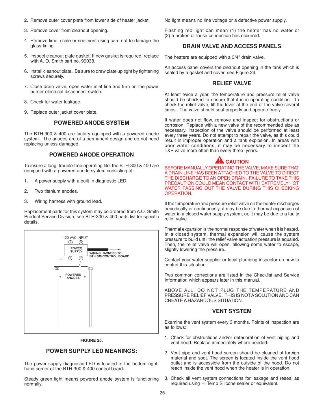
POWERED ANODE OPERATION
To insure a long,
1.A power supply with a
2.Two titanium anodes.
3.Wiring harness with ground lead.
Replacement parts for this system may be ordered from A.O. Smith Product Service Division; see
FIGURE 25.
POWER SUPPLY LED MEANINGS:
The power supply diagnostic LED is located in the bottom right- hand corner of the
Steady green light means powered anode system is functioning normally.
No light means no line voltage or a defective power supply.
Flashing red light can mean (1) the heater has no water or
(2) a broken or loose connection has occurred.
DRAIN VALVE AND ACCESS PANELS
The heaters are equipped with a 3/4" drain valve.
An access panel covers the cleanout opening in the tank which is sealed by a gasket and cover, see Figure 24.
RELIEF VALVE
At least twice a year, the temperature and pressure relief valve should be checked to ensure that it is in operating condition. To check the relief valve, lift the lever at the end of the valve several times. The valve should seat properly and operate freely.
If water does not flow, remove and inspect for obstructions or corrosion. Replace with a new valve of the recommended size as necessary. Inspection of the valve should be performed at least every three years. Do not attempt to repair the valve, as this could result in improper operation and a tank explosion. In areas with poor water conditions, it may be necessary to inspect the T&P valve more often than every three years.
![]() CAUTION
CAUTION
BEFORE MANUALLY OPERATING THE VALVE, MAKE SURE THAT A DRAIN LINE HAS BEEN ATTACHED TO THE VALVE TO DIRECT THE DISCHARGE TO AN OPEN DRAIN. FAILURE TO TAKE THIS PRECAUTION COULD MEAN CONTACT WITH EXTREMELY HOT WATER PASSING OUT THE VALVE DURING THIS CHECKING OPERATION.
If the temperature and pressure relief valve on the heater discharges periodically or continuously, it may be due to thermal expansion of water in a closed water supply system, or, it may be due to a faulty relief valve.
Thermal expansion is the normal response of water when it is heated. In a closed system, thermal expansion will cause the system pressure to build until the relief valve actuation pressure is equaled. Then, the relief valve will open, allowing some water to escape, slightly lowering the pressure.
Contact your water supplier or local plumbing inspector on how to control this situation.
Two common corrections are listed in the Checklist and Service Information which appears later in this manual.
ABOVE ALL, DO NOT PLUG THE TEMPERATURE AND PRESSURE RELIEF VALVE. THIS IS NOT A SOLUTION AND CAN CREATE A HAZARDOUS SITUATION.
VENT SYSTEM
Examine the vent system every 3 months. Points of inspection are as follows:
1.Check for obstructions and/or deterioration of vent piping and vent hood. Replace immediately where needed.
2.Vent pipe and vent hood screen should be cleaned of foreign material and soot. The screen is located inside the vent hood outlet and is accessible from the outside of the hood. Do not reach inside the vent hood when the heater is in operation.
3.Check all vent system connections for leakage and reseal as required using Hi Temp Silicone sealer or equivalent.
25