A.O. Smith DB/DW-720-1810 warranty Systems Equipment Installation

Models: DB/DW-720-1810

1 44
Download 44 pages 15.17 Kb
Page 12
Image 12

IF ANY OF THE ORIGINAL WIRE, AS SUPPLIED WITH THE APPLIANCE, MUST BE REPLACED, IT MUST BE REPLACED WITH TYPE 105°C WIRE OR ITS EQUIVALENT, EXCEPT FOR THE FLAME SENSOR AND IGNITION CABLE WHICH ARE 250°C.

SERVICING WIRING AND/OR CONTROL

CAUTION

Label all wires prior to disconnection when servicing controls. Wiring errors can cause improper and dangerous operation.

Verify proper operation after servicing.

SYSTEMS EQUIPMENT

INSTALLATION

SYSTEM HEADERS

Split systems with individual supply and return lines from the boiler room should normally have this piping connected to supply and return manifold headers near the boiler. To achieve good water distribution with minimum pressure drop for several circuits, manifolds should be larger than system loops.

The circuits should be spaced on the header at a minimum of 3" (76 mm) center to center. Install a balancing cock in each return line.

Manifold headers are recommended for split systems with or without zone valves and also those installations with zone circulators. If the system is to be split at remote points, good practice requires special attention be given to main pipe sizing to allow balancing of water flow.

COOLING PIPING

The following is a brief description of the equipment required for installations noted in this manual. All installations must comply with local codes.

The boilers described in this manual may be used for space heating or for the heating of potable water. If the heater is to be used for hydronic space heating, follow the descriptions given for equipment required for installation on pages 12 through 31. However, if units are to be used for heating potable water, the information describing specific systems is found starting on page 32. Installations must comply with all local codes.

WATER SUPPLY LINE

These boilers can be used ONLY in a forced circulation hot water heating system. Since most forced circulation systems will be of the closed type, install the water supply line as shown on piping diagrams, fig’s. 10 and 14.

Fast filling of large pipe, old radiator installations (where high pressures are not available) requires bypassing of the pressure reducing valve. Generally, pressure purging is not possible with a well pump system. High point air venting is essential. For details, refer to OPERATING INSTRUCTIONS section of this manual.

If the system is of the open type, a pressure reducing valve will not be required as the water supply to the system will be controlled by a manually operated valve. An overhead surge tank is required. A MINIMUM PRESSURE OF 15 PSI MUST BE MAINTAINED ON THE BOILER AT ALL TIMES to ensure avoidance of potential damage to the boiler which may not be covered by the warranty.

EXPANSION TANK

If the system is of the closed type, install an expansion tank as shown in fig. 10. The sizing of the expansion tank for a closed system is very important and is directly related to the total water volume of the system. Refer to ASME or other reliable specifications for sizing.

An air separator as shown in the piping diagrams is recom- mended especially for modern commercial hydronic systems.

VENT VALVES

It is recommended that automatic, loose key or screwdriver type vent valves be installed at each convector or radiator.

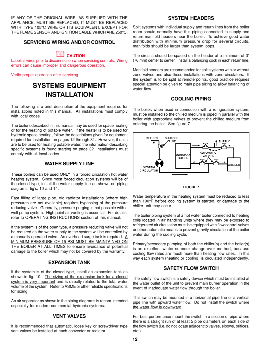
The boiler, when used in connection with a refrigeration system, must be installed so the chilled medium is piped in parallel with the boiler with appropriate valves to prevent the chilled medium from entering the boiler. See figure 7.

FIGURE 7

Water temperature in the heating system must be reduced to less than 100°F before cooling system is started, or damage to the chiller unit may occur.

The boiler piping system of a hot water boiler connected to heating coils located in air handling units where they may be exposed to refrigerated air circulation must be equipped with flow control valves or other automatic means to prevent gravity circulation of the boiler water during the cooling cycle.

Primary/secondary pumping of both the chiller(s) and the boiler(s) is an excellent winter-summer change-over method, because cooling flow rates are much more than heating flow rates. In this way each system (heating or cooling) is circulated independently.

SAFETY FLOW SWITCH

The safety flow switch is a safety device which must be installed at the water outlet of the unit to prevent main burner operation in the event of inadequate water flow through the boiler.

This switch may be mounted in a horizontal pipe line or a vertical pipe line with upward water flow. Do not install the switch where the water flow is downward.

For best performance mount the switch in a section of pipe where there is a straight run of at least 5 pipe diameters on each side of the flow switch (i.e. do not locate adjacent to valves, elbows, orifices, etc.).

12

Page 12
Image 12
A.O. Smith DB/DW-720-1810 warranty Systems Equipment Installation

DB/DW-720-1810 specifications

A.O. Smith has a longstanding reputation for quality and innovation in the water heater industry, and the DB/DW-720-1810 model exemplifies these values. This particular water heater is designed to provide reliable hot water, making it suitable for both residential and commercial applications. Its impressive features and cutting-edge technologies set it apart from conventional models.

One of the primary features of the A.O. Smith DB/DW-720-1810 is its energy efficiency. It operates using advanced insulation technologies, minimizing heat loss and promoting energy savings. This model is designed with a high-efficiency burner that substantially reduces energy consumption while maintaining optimal performance. It also complies with industry standards for energy efficiency, ensuring that users can enjoy lower utility bills without sacrificing comfort.

The DB/DW-720-1810 is equipped with a robust tank designed to hold an ample supply of hot water. With a capacity of 75 gallons, it is ideal for households with high demand, such as multi-bathroom residences or commercial establishments. This large capacity ensures that hot water is readily available for various activities, from bathing to cleaning.

User control is another notable characteristic of the A.O. Smith DB/DW-720-1810. The model features an intuitive digital display that allows users to monitor and set water temperatures easily. This interface not only enhances usability but also promotes safety, preventing scalding by allowing users to adjust the temperature to their preference.

Durability is a key consideration in the DB/DW-720-1810’s design. It is built with high-quality materials and features a corrosion-resistant tank, ensuring longevity even in challenging water conditions. This resilience is further supplemented by A.O. Smith's advanced anode rod technology, which helps battle corrosion and extends the lifespan of the water heater.

Lastly, maintenance is simplified with this model. A.O. Smith has designed the water heater for easy access to serviceable parts, making routine maintenance more convenient and less time-consuming. Coupled with warranty options that provide peace of mind, the DB/DW-720-1810 stands out as a dependable choice.

In summary, the A.O. Smith DB/DW-720-1810 combines energy efficiency, significant capacity, user-friendly controls, durability, and low maintenance needs, making it an exceptional option for those needing a reliable hot water solution.