SDV, FDVT, FDV specifications
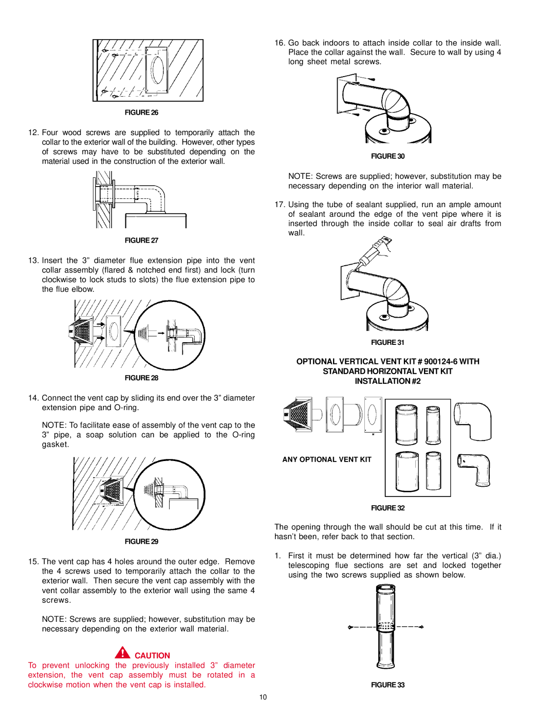
A.O. Smith is a leading name in the water heating industry, known for its innovative products and commitment to quality. Among its extensive lineup, the FDV, FDVT, and SDV series stand out due to their advanced features and technologies designed to enhance performance and efficiency.The FDV series represents a revolution in traditional water heating solutions. These direct vent water heaters are designed to provide hot water on demand while minimizing energy consumption. The FDV models utilize a dual venting system, allowing for the efficient expulsion of combustion gases outside the home while drawing in fresh air for the combustion process. This design increases efficiency by ensuring optimal combustion and improves safety by reducing the risk of indoor air contamination.
The FDVT series builds upon the innovative features of the FDV, integrating a tankless design that provides unlimited hot water. This makes it an ideal choice for households with higher hot water demands. The FDVT models use high-efficiency burners and advanced heat exchangers to deliver hot water quickly and consistently, adapting to varying flow rates. They are also equipped with intelligent control systems that monitor water usage patterns and adjust operation accordingly, optimizing energy efficiency without sacrificing performance.
The SDV series caters to those looking for a reliable and efficient storage tank water heater. With a robust construction and reliable design, these water heaters are built to last. The SDV models are designed with high-quality insulation to minimize heat loss, making them energy-efficient options for storing hot water. Additional features include built-in safety mechanisms, such as temperature and pressure relief valves, ensuring safe operation at all times.
A.O. Smith's commitment to innovation is evident in their use of cutting-edge technologies across these series. Both the FDV and FDVT models incorporate sophisticated electronic controls, enabling features like scheduling and remote access for greater convenience. They are compatible with smart home systems, allowing users to monitor and manage water heating remotely.
In terms of energy efficiency, models within these series are designed to exceed industry standards, often qualifying for energy rebates and incentives in various regions. With features such as modulating burners, they adjust the energy input based on demand, significantly reducing operational costs.
Overall, A.O. Smith's FDV, FDVT, and SDV series represent leading-edge solutions in water heating, combining efficiency, safety, and advanced technology to meet the diverse needs of modern households. Whether seeking endless hot water or reliable storage solutions, these series offer unparalleled options that prioritize performance and sustainability.

