TABLE 2.

E DIMENSIONS


40-50 Gal.

75 Gal.

VENT KITS


MIN.


MAX.

MIN.

MAX.


900068-7-STD.

3-1/2


10


7/8

7-3/8


900124-6


10


15-1/2


7-3/8

12-7/8


900124-7


15-1/2


26-1/2


12-7/8

23-7/8

900124-8


26-1/2


48


23-7/8

45-3/8


*BTU’S in


*GAL.


1000’s


CAP.


NAT/L.P.


A


B

C

40


36/36


48-3/4


41-3/4

21

50


38/38


57-1/2


50-1/2

21

40


40/40


48-3/4


41-3/4

21

50


48/44


61


54

21

75


55 NAT.


63


54-3/4

26-1/4

*See models and rating plate attached to the water heater for specific model number and other detailed information.

WARNING

Be sure vent pipe is properly connected to prevent escape of dangerous flue gases which could cause deadly asphyxiation.

ALL INSTALLATIONS

For ease of assembly the installation of the various kit combinations has been broken into individual sections. The two steps below are common to all installations. Once these have been performed, you need only to refer to the type installation that pertains to you.

Installation Using Vent Kits:


1.

Standard Vent Kit

Page 8

2.

Optional Vertical Vent Kit

Page 10


with Standard Vent Kit


3.

Optional Horizontal Vent Kit

Page 13

4.

Optional Horizontal and

Page 15


Vertical Vent Kits


CUTTING THE OPENING THROUGH

THE OUTSIDE WALL

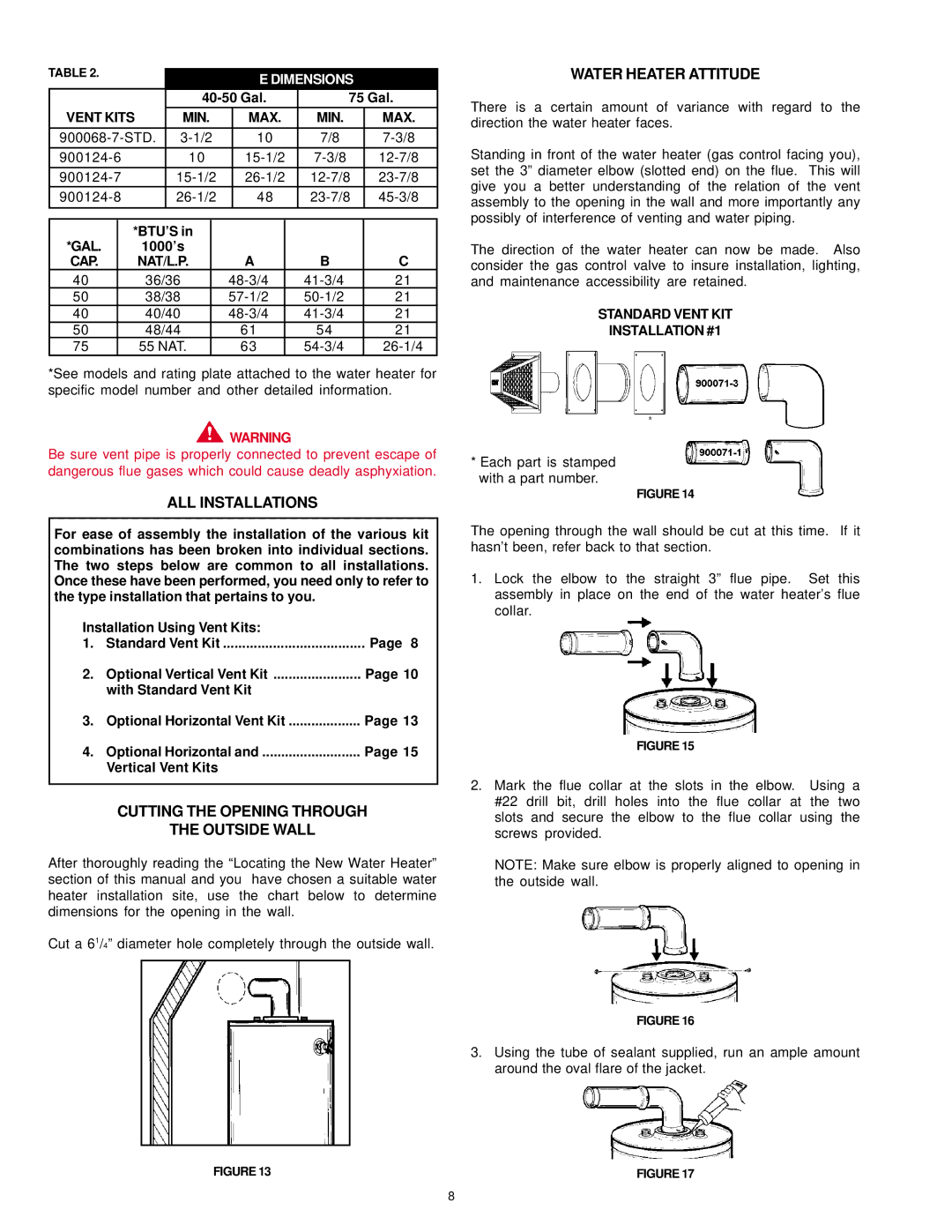
After thoroughly reading the “Locating the New Water Heater” section of this manual and you have chosen a suitable water heater installation site, use the chart below to determine dimensions for the opening in the wall.

Cut a 61/4” diameter hole completely through the outside wall.

WATER HEATER ATTITUDE

There is a certain amount of variance with regard to the direction the water heater faces.

Standing in front of the water heater (gas control facing you), set the 3” diameter elbow (slotted end) on the flue. This will give you a better understanding of the relation of the vent assembly to the opening in the wall and more importantly any possibly of interference of venting and water piping.

The direction of the water heater can now be made. Also consider the gas control valve to insure installation, lighting, and maintenance accessibility are retained.

STANDARD VENT KIT

INSTALLATION #1

*Each part is stamped with a part number.

FIGURE 14

The opening through the wall should be cut at this time. If it hasn’t been, refer back to that section.

1.Lock the elbow to the straight 3” flue pipe. Set this assembly in place on the end of the water heater’s flue collar.

FIGURE 15

2.Mark the flue collar at the slots in the elbow. Using a #22 drill bit, drill holes into the flue collar at the two slots and secure the elbow to the flue collar using the screws provided.

NOTE: Make sure elbow is properly aligned to opening in the outside wall.

FIGURE 16

3.Using the tube of sealant supplied, run an ample amount around the oval flare of the jacket.

FIGURE 13

FIGURE 17

8

Page 8
Image 8
A.O. Smith SDV, FDVT owner manual ALL Installations, Cutting the Opening Through Outside Wall, Water Heater Attitude

SDV, FDVT, FDV specifications

A.O. Smith is a leading name in the water heating industry, known for its innovative products and commitment to quality. Among its extensive lineup, the FDV, FDVT, and SDV series stand out due to their advanced features and technologies designed to enhance performance and efficiency.

The FDV series represents a revolution in traditional water heating solutions. These direct vent water heaters are designed to provide hot water on demand while minimizing energy consumption. The FDV models utilize a dual venting system, allowing for the efficient expulsion of combustion gases outside the home while drawing in fresh air for the combustion process. This design increases efficiency by ensuring optimal combustion and improves safety by reducing the risk of indoor air contamination.

The FDVT series builds upon the innovative features of the FDV, integrating a tankless design that provides unlimited hot water. This makes it an ideal choice for households with higher hot water demands. The FDVT models use high-efficiency burners and advanced heat exchangers to deliver hot water quickly and consistently, adapting to varying flow rates. They are also equipped with intelligent control systems that monitor water usage patterns and adjust operation accordingly, optimizing energy efficiency without sacrificing performance.

The SDV series caters to those looking for a reliable and efficient storage tank water heater. With a robust construction and reliable design, these water heaters are built to last. The SDV models are designed with high-quality insulation to minimize heat loss, making them energy-efficient options for storing hot water. Additional features include built-in safety mechanisms, such as temperature and pressure relief valves, ensuring safe operation at all times.

A.O. Smith's commitment to innovation is evident in their use of cutting-edge technologies across these series. Both the FDV and FDVT models incorporate sophisticated electronic controls, enabling features like scheduling and remote access for greater convenience. They are compatible with smart home systems, allowing users to monitor and manage water heating remotely.

In terms of energy efficiency, models within these series are designed to exceed industry standards, often qualifying for energy rebates and incentives in various regions. With features such as modulating burners, they adjust the energy input based on demand, significantly reducing operational costs.

Overall, A.O. Smith's FDV, FDVT, and SDV series represent leading-edge solutions in water heating, combining efficiency, safety, and advanced technology to meet the diverse needs of modern households. Whether seeking endless hot water or reliable storage solutions, these series offer unparalleled options that prioritize performance and sustainability.