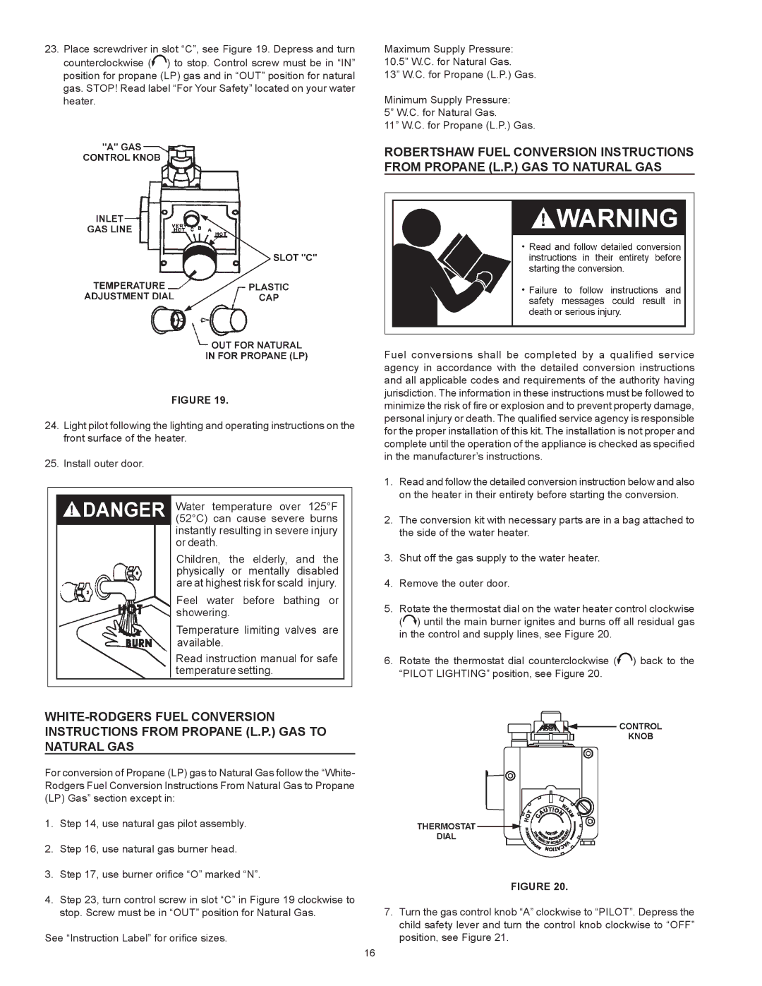
23.Place screwdriver in slot “C”, see Figure 19. Depress and turn counterclockwise (![]() ) to stop. Control screw must be in “IN” position for propane (LP) gas and in “OUT” position for natural gas. STOP! Read label “For Your Safety” located on your water heater.
) to stop. Control screw must be in “IN” position for propane (LP) gas and in “OUT” position for natural gas. STOP! Read label “For Your Safety” located on your water heater.
FIGURE 19.
24.Light pilot following the lighting and operating instructions on the front surface of the heater.
25.Install outer door.
Maximum Supply Pressure: 10.5” W.C. for Natural Gas.
13” W.C. for Propane (L.P.) Gas.
Minimum Supply Pressure: 5” W.C. for Natural Gas.
11” W.C. for Propane (L.P.) Gas.
ROBERTSHAW FUEL CONVERSION INSTRUCTIONS FROM PROPANE (l.p.) gAS TO NATURAL GAS
Fuel conversions shall be completed by a qualified service agency in accordance with the detailed conversion instructions and all applicable codes and requirements of the authority having jurisdiction. The information in these instructions must be followed to minimize the risk of fire or explosion and to prevent property damage, personal injury or death. The qualified service agency is responsible for the proper installation of this kit. The installation is not proper and complete until the operation of the appliance is checked as specified in the manufacturer’s instructions.
1.Read and follow the detailed conversion instruction below and also on the heater in their entirety before starting the conversion.
2.The conversion kit with necessary parts are in a bag attached to the side of the water heater.
3.Shut off the gas supply to the water heater.
4.Remove the outer door.
5.Rotate the thermostat dial on the water heater control clockwise (![]() ) until the main burner ignites and burns off all residual gas in the control and supply lines, see Figure 20.
) until the main burner ignites and burns off all residual gas in the control and supply lines, see Figure 20.
6.Rotate the thermostat dial counterclockwise (![]() ) back to the “PILOT LIGHTING” position, see Figure 20.
) back to the “PILOT LIGHTING” position, see Figure 20.
For conversion of Propane (LP) gas to Natural Gas follow the “White- Rodgers Fuel Conversion Instructions From Natural Gas to Propane (LP) Gas” section except in:
1.Step 14, use natural gas pilot assembly.
2.Step 16, use natural gas burner head.
3.Step 17, use burner orifice “O” marked “N”.
4.Step 23, turn control screw in slot “C” in Figure 19 clockwise to stop. Screw must be in “OUT” position for Natural Gas.
See “Instruction Label” for orifice sizes.
FIGURE 20.
7.Turn the gas control knob “A” clockwise to “PILOT”. Depress the child safety lever and turn the control knob clockwise to “OFF” position, see Figure 21.
16
