For protection against excessive pressures and temperatures, a temperature and pressure relief valve must be installed in the opening marked “T & P RELIEF VALVE” (see Figure 15A). This valve must be design certified by
a nationally recognized testing laboratory that maintains periodic inspection of the production of listed equipment or materials as meeting the requirements for Relief Valves for Hot Water Supply Systems, ANSI Z21.22. The function of the temperature and pressure relief valve is to discharge water in large quantities in the event of excessive temperature or pressure developing in the water heater. The valve’s relief pressure must not exceed the working pressure of the water heater as stated on the rating plate.
IMPORTANT: Only a new temperature and pressure relief valve should be used with your water heater. Do not use an old or existing valve as it may be damaged or not adequate for the working pressure of the new water heater. Do not place any valve between the relief valve and the tank.
The Temperature & Pressure Relief Valve:
•Must not be in contact with any electrical part.
•Must be connected to an adequate discharge line.
•Must not be rated higher than the working pressure shown on the rating plate of the water heater.
The Discharge Line:
•Must not be smaller than the pipe size of the relief valve or have any reducing coupling installed in the discharge line.
•Must not be capped, blocked, plugged or contain any valve between the relief valve and the end of the dis- charge line.
•Must terminate a maximum of six inches above a floor drain or external to the building. In cold climates, it is recommended that the discharge pipe be terminated at an adequate drain inside the building.
•Must be capable of withstanding 250°F (121°C) without distortion.
•Must be installed to allow complete drainage of both the valve and discharge line.
T&P Relief Valve and Pipe Insulation
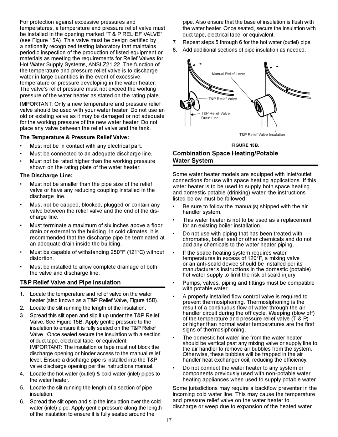
1.Locate the temperature and relief valve on the water heater (also known as a T&P Relief Valve, Figure 15B).
2.Locate the slit running the length of the insulation.
3Spread this slit open and slip it up under the T&P Relief Valve. See Figure 15B. Apply gentle pressure to the insulation to ensure it is fully seated on the T&P Relief Valve. Once sealed secure the insulation with a section of duct tape, electrical tape, or equivalent. IMPORTANT: The insulation or tape must not block the discharge opening or hinder access to the manual relief lever. Ensure a discharge pipe is installed into the T&P valve discharge opening per the instructions manual.
4.Locate the hot water (outlet) & cold water (inlet) pipes to the water heater.
5.Locate the slit running the length of a section of pipe insulation.
6.Spread the slit open and slip the insulation over the cold water (inlet) pipe. Apply gentle pressure along the length of the insulation to ensure it is fully seated around the
pipe. Also ensure that the base of insulation is flush with the water heater. Once seated, secure the insulation with duct tape, electrical tape, or equivalent.
7.Repeat steps 5 through 6 for the hot water (outlet) pipe.
8.Add additional sections of pipe insulation as needed.
Manual Relief Lever
T&P Relief Valve |
![]() T&P Relief Valve
T&P Relief Valve
Drain Line
T&P Relief Valve Insulation
FIGURE 15B.
Combination Space Heating/Potable
Water System
Some water heater models are equipped with inlet/outlet connections for use with space heating applications. If this water heater is to be used to supply both space heating and domestic potable (drinking) water, the instructions listed below must be followed.
•Be sure to follow the manual(s) shipped with the air handler system.
•This water heater is not to be used as a replacement for an existing boiler installation.
•Do not use with piping that has been treated with chromates, boiler seal or other chemicals and do not add any chemicals to the water heater piping.
•If the space heating system requires water temperatures in excess of 120°F, a mixing valve or an
•Pumps, valves, piping and fittings must be compatible with potable water.
•A properly installed flow control valve is required to prevent thermosiphoning. Thermosiphoning is the result of a continuous flow of water through the air handler circuit during the off cycle. Weeping (blow off) of the temperature and pressure relief valve (T & P) or higher than normal water temperatures are the first signs of thermosiphoning.
•The domestic hot water line from the water heater should be vertical past any mixing valve or supply line to the air handler to remove air bubbles from the system. Otherwise, these bubbles will be trapped in the air handler heat exchanger coil, reducing the efficiency.
•Do not connect the water heater to any system or components previously used with
Some jurisdictions may require a backflow preventer in the incoming cold water line. This may cause the temperature and pressure relief valve on the water heater to discharge or weep due to expansion of the heated water.
17