cont.
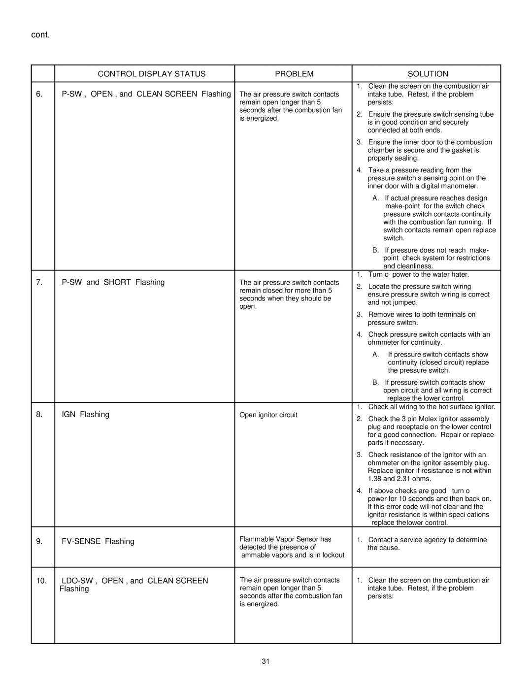
| CONTROL DISPLAY STATUS | PROBLEM |
| SOLUTION | |
|
|
|
|
| |
6. |
|
| 1. | Clean the screen on the combustion air | |
The air pressure switch contacts |
| intake tube. Retest, if the problem | |||
|
| remain open longer than 5 |
| persists: | |
|
| seconds after the combustion fan | 2. | Ensure the pressure switch sensing tube | |
|
| is energized. | |||
|
|
| is in good condition and securely | ||
|
|
|
| ||
|
|
|
| connected at both ends. | |
|
|
| 3. | Ensure the inner door to the combustion | |
|
|
|
| chamber is secure and the gasket is | |
|
|
|
| properly sealing. | |
|
|
| 4. | Take a pressure reading from the | |
|
|
|
| pressure switch’s sensing point on the | |
|
|
|
| inner door with a digital manometer. | |
|
|
|
| A. If actual pressure reaches design | |
|
|
|
| ||
|
|
|
| pressure switch contacts continuity | |
|
|
|
| with the combustion fan running. If | |
|
|
|
| switch contacts remain open replace | |
|
|
|
| switch. | |
|
|
|
| B. If pressure does not reach “make- | |
|
|
|
| point” check system for restrictions | |
|
|
|
| and cleanliness. | |
7. |
| The air pressure switch contacts | 1. | Turn off power to the water hater. | |
2. | Locate the pressure switch wiring – | ||||
|
| remain closed for more than 5 | |||
|
|
| ensure pressure switch wiring is correct | ||
|
| seconds when they should be |
| ||
|
|
| and not jumped. | ||
|
| open. |
| ||
|
| 3. | Remove wires to both terminals on | ||
|
|
| |||
|
|
|
| pressure switch. | |
|
|
| 4. | Check pressure switch contacts with an | |
|
|
|
| ohmmeter for continuity. | |
|
|
|
| A. If pressure switch contacts show | |
|
|
|
| continuity (closed circuit) replace | |
|
|
|
| the pressure switch. | |
|
|
|
| B. If pressure switch contacts show | |
|
|
|
| open circuit and all wiring is correct | |
|
|
|
| – replace the lower control. | |
8. | “IGN” Flashing | Open ignitor circuit | 1. | Check all wiring to the hot surface ignitor. | |
2. | Check the 3 pin Molex ignitor assembly | ||||
|
|
| |||
|
|
|
| plug and receptacle on the lower control | |
|
|
|
| for a good connection. Repair or replace | |
|
|
|
| parts if necessary. | |
|
|
| 3. | Check resistance of the ignitor with an | |
|
|
|
| ohmmeter on the ignitor assembly plug. | |
|
|
|
| Replace ignitor if resistance is not within | |
|
|
|
| 1.38 and 2.31 ohms. | |
|
|
| 4. | If above checks are good – turn off | |
|
|
|
| power for 10 seconds and then back on. | |
|
|
|
| If this error code will not clear and the | |
|
|
|
| ignitor resistance is within specifications | |
|
|
|
| – replace the lower control. | |
9. |
| Flammable Vapor Sensor has | 1. | Contact a service agency to determine | |
|
| detected the presence of |
| the cause. | |
|
| flammable vapors and is in lockout |
|
| |
|
|
|
|
| |
10. | The air pressure switch contacts | 1. | Clean the screen on the combustion air | ||
| Flashing | remain open longer than 5 |
| intake tube. Retest, if the problem | |
|
| seconds after the combustion fan |
| persists: | |
|
| is energized. |
|
| |
|
|
|
|
|
31
