Measure the incoming gas pressure. -Minimum inlet gas supply pressure of 4” w.c. and maximum is 11.0 for natural gas or 8” w.c. min and 13.8 max for propane. The maximum value specified must not be exceeded under both load and no load conditions. If this condition can not be obtained a positive lock-up type pressure regulator MUST be installed approximately five feet away from the gas valve of the boiler and per the regulator manufacture’s instructions.

Check all gas supply lines for leaks.

Check that all venting is properly installed in accordance with the venting section of the instruction manual.

Follow the lighting and operating instructions in the Instruction Manual.

IV. Boiler Start-Up

Starting the boiler for the first time

-The boiler is tested at the factory and should start properly if installed in accordance with the boiler’s instruction manual.

-Before starting the boiler, refer to the temperature set-point procedure section in the boilers instruction manual.

-Turn on the boiler’s on/off switch. Ensure the operating set point is set high enough to activate a call for heat. If an external control is using the boiler’s Enable/Disable circuit, ensure that the external control’s contacts are closed. If there is no external control, ensure that the two wires provided for this circuit are wire-nutted together in the junction box on the back of the boiler. Refer to the wiring diagram on the boiler.

-Allow the unit to run for at least 10 minutes before proceeding with the combustion analysis. Take a combustion sample and record CO and CO2 or O2 readings.

Setting of the test mode

-On UIM go to main menu, scroll down to user settings and press select. Scroll down to MOD mode, press select. Use the up and down keys to select options: MIN (MINIMUM FIRING RATE). MAX (MAXIMUM FIRING RATE). MOD (FOR AUTOMATIC MODULATION MODE). Press select for the desired option. For checking the combustion setup on MIN or MAX the boiler will remain in this state for 20 minutes before defaulting to the MOD (modulation) mode.

MAXIMUM FIRE ADJUSTMENT - Combustion sample

-First set boiler to the “Test Mode Max,” as described above, to achieve maximum firing rate of the boiler. Check combustion readings using a combustion analyzer. If combustion readings are not in accordance with the chart below adjust as follows: remove the flat, round, blue plastic cap from the cover. Using a 3mm (7/64”) hex wrench, turn the adjustment screw counterclockwise to increase or clockwise to decrease gas flow and achieve the desired CO2 level. See Table referenced below for correct settings. There will be a slight time delay between the adjustment and the response of the CO2 measuring instrument. Adjust the settings in small 1/16 increments and allow the combustion readings to stabilize before readjusting. When desired adjustments are complete, reinstall the blue plastic cap on the cover. Combustion samples shall be taken within 8 inches from the rear boiler.

IMPROPER ADJUSTMENT CAN CAUSE INCOMPLETE COMBUSTION RESULTING IN DEATH.

MINIMUM FIRE ADJUSTMENT - Combustion sample

-Next set boiler to the “Test Mode Min,” as described above, to achieve minimum firing rate of the boiler. Check combustion readings using a combustion analyzer. If combustion readings are not in accordance with the chart shown below adjust as follows: remove the metal cap on the gas regulator using a slotted screwdriver. This will expose the offset adjustment screw. Using a TORX® T40 or a 5mm hex wrench, carefully adjust the low fire gas setting to achieve the CO2 level prescribed in below reference table. Note: The rotation of the Low Fire adjustment is opposite of the High Fire as follows: Clockwise rotation increases gas flow, counterclockwise rotation decreases gas flow. Adjustments to the offset pressure regulators should not exceed 1/16 increments at a time before allowing the readings to respond and stabilize. After proper low fire offset adjustment is made, reinstall the slotted cap on the regulator.

Following all gas valve adjustments, check for proper light-off and verify correct fuel/air mix during test mode procedure prescribed above.

If adjustments have been made, repeat the combustion sampling using the “Test Mode” procedure to insure that the readings remain within the ranges. If the readings are not in accordance repeat the High and Low fire adjustment procedure.

IMPORTANT!! The Min Mode and Max Mode are used for checking combustion during start up. Return boiler to Mod Mode after checking combustion.

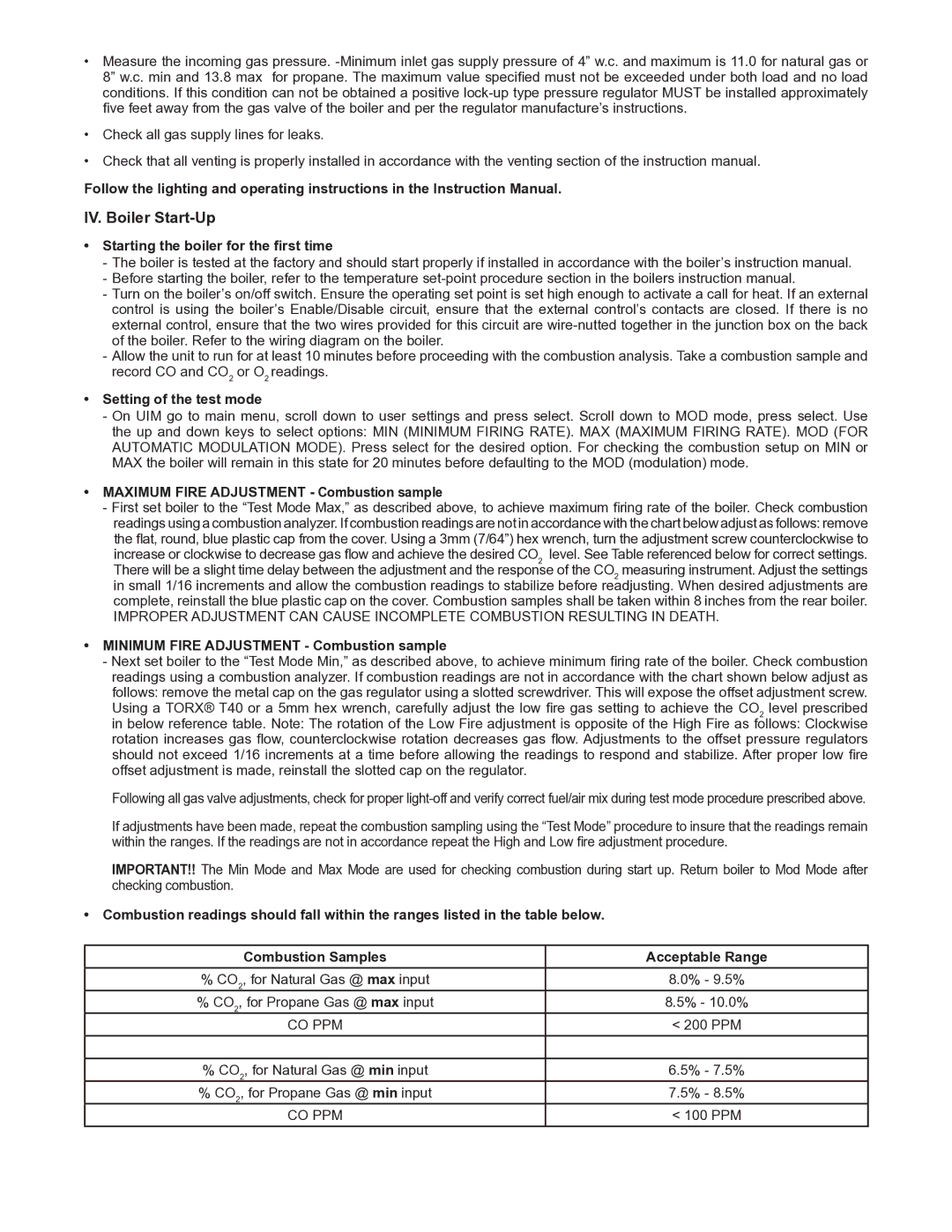
Combustion readings should fall within the ranges listed in the table below.

Combustion Samples

Acceptable Range

% CO2, for Natural Gas @ max input

8.0% - 9.5%

% CO2, for Propane Gas @ max input

8.5% - 10.0%

CO PPM

< 200 PPM


% CO2, for Natural Gas @ min input

6.5% - 7.5%

% CO2, for Propane Gas @ min input

7.5% - 8.5%

CO PPM

< 100 PPM

Page 2
Image 2
A.O. Smith VB/VW 500/750/1000 IV. Boiler Start-Up, Starting the boiler for the first time, Setting of the test mode

VB/VW 500/750/1000 specifications

A.O. Smith is a well-known name in the water heating industry, and its VB/VW series models, particularly the 500, 750, and 1000, are designed for commercial applications, offering a range of advanced features and technologies. These models are recognized for their high efficiency, reliability, and performance, making them suitable for various industries, including hospitality, healthcare, and food service.

One of the standout features of the VB/VW series is their impressive recovery rates. With a powerful heating capacity, these units can deliver hot water consistently, ensuring that large demands are met without interruptions. This is particularly important for businesses that rely on a steady supply of hot water throughout the day.

The VB/VW series utilizes advanced insulation technology, which significantly reduces energy loss. This feature not only improves the overall energy efficiency of the units but also contributes to lower operational costs. The use of foam insulation helps maintain water temperature, allowing for reduced energy consumption and enhanced performance.

These models come equipped with advanced control systems, providing users with greater flexibility and ease of operation. The user-friendly digital display allows for precise temperature control and monitoring, ensuring optimal performance is maintained at all times. Additionally, the temperature settings can be adjusted to suit specific water heating requirements, catering to the unique needs of various applications.

A.O. Smith's commitment to safety is evident in the design of the VB/VW series. These models incorporate multiple safety features, including a high-temperature limit switch, fusible links, and proper venting systems, ensuring safe operation in any environment. The robust construction of the units, combined with the use of high-quality materials, enhances durability and extends the lifespan of the water heaters.

Moreover, these models are designed for easy maintenance. The intuitive design allows for simplified access to key components, making routine checks and servicing straightforward for technicians. This ease of maintenance contributes to reduced downtime and enhances the overall operational efficiency of the water heating system.

In summary, the A.O. Smith VB/VW 500, 750, and 1000 water heaters are engineered to meet the demands of commercial applications with their high efficiency, advanced technology, and safety features. With their ability to deliver consistent hot water, coupled with ease of maintenance and reduced energy consumption, these models stand out as a reliable choice for businesses seeking efficient and effective water heating solutions.