Water Heater specifications
A.O. Smith is a renowned name in the water heating industry, celebrated for its commitment to innovation, quality, and efficiency. Their water heaters are designed to cater to a wide variety of needs, making them suitable for both residential and commercial applications. The main features of A.O. Smith water heaters are tailored to ensure optimal performance, convenience, and reliability.One of the standout characteristics of A.O. Smith water heaters is their impressive energy efficiency. Many models are equipped with advanced insulation technologies that minimize heat loss, allowing users to save on energy bills while ensuring a consistent supply of hot water. The introduction of high-efficiency gas burners and electric heating elements enhances their energy utilization, which is reflected in their excellent Energy Factor ratings.
A.O. Smith also incorporates smart technology in its water heaters. Many models feature integrated Wi-Fi connectivity, allowing homeowners to monitor and control their water heating system remotely via a smartphone app. This capability enables users to adjust temperature settings, receive maintenance alerts, and track energy usage, providing a new level of convenience and control.
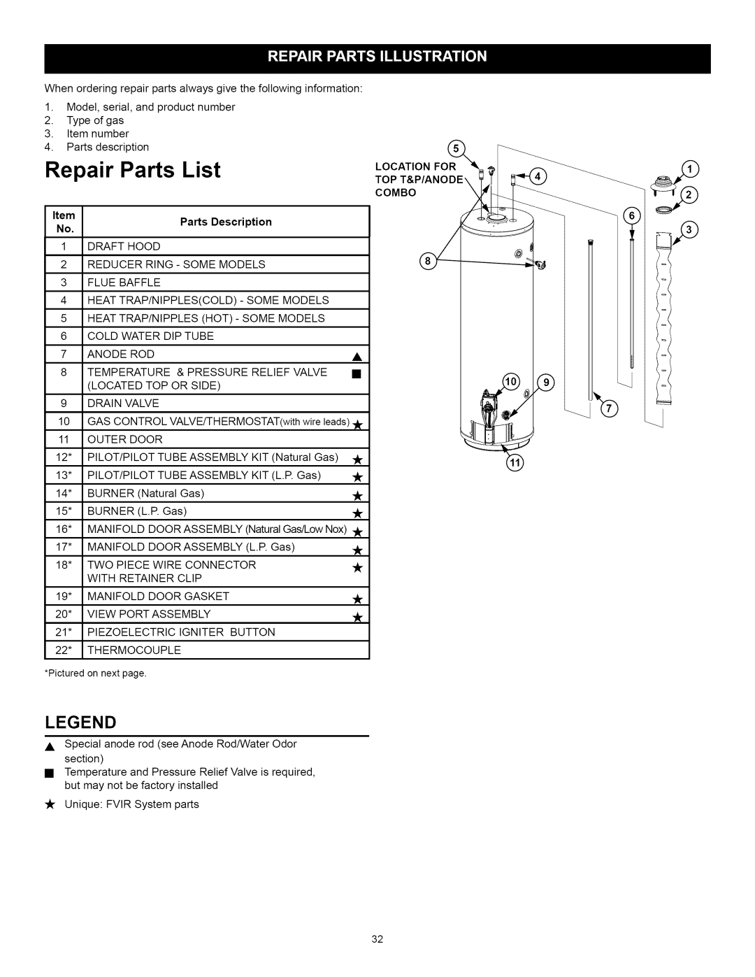
Durability is another hallmark of A.O. Smith water heaters. Constructed with high-quality materials, these units often feature a glass-lined tank that enhances corrosion resistance. Additionally, many models are designed with a robust anode rod that helps prevent rusting, extending the lifespan of the heater and ensuring dependable service for years to come.
Safety features are also a priority for A.O. Smith. Many water heaters come equipped with advanced safety mechanisms, such as automatic shut-off valves, temperature controls, and flame failure detection systems, ensuring safe operation and reducing the risk of accidents.
Different models are available to suit varying space requirements and preferences. A.O. Smith produces traditional tank water heaters as well as modern tankless options, which provide endless hot water on demand, making them ideal for homes needing high hot water consumption. Their versatility guarantees that customers can find the perfect solution tailored to their specific needs.
In conclusion, A.O. Smith water heaters represent a blend of innovation, efficiency, durability, and safety. With various models available that cater to different heating needs and preferences, A.O. Smith continues to remain a trusted choice for consumers seeking reliable hot water solutions.

