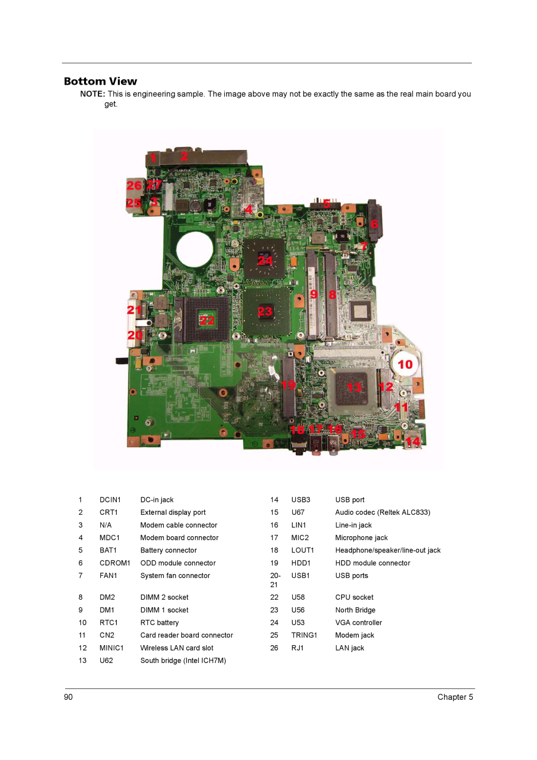
Bottom View
NOTE: This is engineering sample. The image above may not be exactly the same as the real main board you get.
1 | DCIN1 | 14 | USB3 | USB port | |
2 | CRT1 | External display port | 15 | U67 | Audio codec (Reltek ALC833) |
3 | N/A | Modem cable connector | 16 | LIN1 | |
4 | MDC1 | Modem board connector | 17 | MIC2 | Microphone jack |
5 | BAT1 | Battery connector | 18 | LOUT1 | |
6 | CDROM1 | ODD module connector | 19 | HDD1 | HDD module connector |
7 | FAN1 | System fan connector | 20- | USB1 | USB ports |
|
|
| 21 |
|
|
8 | DM2 | DIMM 2 socket | 22 | U58 | CPU socket |
9 | DM1 | DIMM 1 socket | 23 | U56 | North Bridge |
10 | RTC1 | RTC battery | 24 | U53 | VGA controller |
11 | CN2 | Card reader board connector | 25 | TRING1 | Modem jack |
12 | MINIC1 | Wireless LAN card slot | 26 | RJ1 | LAN jack |
13 | U62 | South bridge (Intel ICH7M) |
|
|
|
90 | Chapter 5 |
