Serviceguide
Revision History
Conventions
General information
Chapter
System Utilities
Machine Maintenance Procedures
Troubleshooting
Field Replaceable Unit List
Page
Chapter
Features
Page
Page
Features
Graphics
Privacy Control
Optical Media Drive N/A Communication
Webcam
Dimension and Weight
Power Adapter and Battery
Ports
Special Keys and Controls
Environment
Warranty
Optional Items
Software
Top View
Top View Icon Description
Top View Icon Description
Closed Front View
Blue light on
Orange light on
Not lit
Rear View
Left View
Left View Icon Description
Right View
Right View Icon Description
Base View
Base View Icon Description
Hardware Specifications and Configurations
Touchpad Basics
Touchpad Function Main TouchPad Left Button Right Button
Using the Keyboard
Keyboard Lock Keys Lock key Description
10. Windows Keys Description
Windows Keys
Functions supported by Windows XP
Hotkeys
11. Keyboard Hotkeys Hot key Icon Function Description
Fn + F11 only for certain
Keyboard Hotkeys Hot key Icon Function Description
Models
Using the Communication Key
10. Launch Manager Dialog
System Block Diagram
11. System Block Diagram
Specification Tables
Computer specifications Metric Imperial
System Board Major Chips Specification
Processor Specification
Processor Specifications
Cores Bus Mfg Cache Package Voltage GHz Threads
System Memory Specification
Ddriii
Video Interface Specification
Memory Combinations Slot 1 MB Total Memory MB
Lvds
TBD
LAN Interface Specification
MAC Features
Device and Technology Features
PHY Features
Pcie Features
Specification LAN Interface Host Offloading Features
Keyboard Specification
Hard Disk Drive AVL components Specification
Specification Hard Disk Drive
BD Drive not available with this model Items Specifications
LED Specification
LCD Inverter not available with this model Specification
Bluetooth Interface Specifications
Graphics Controller Specification
SM06B-XSRK-ETB
Bluetooth Module Specifications
Camera Specification
Mini Card Specification
3G Card Specification
Specification Audio Codec and Amplifier
Specification Audio Codec and Amplifier
Audio Interface Specification
Wireless Module 802.11b/g/n Specification
Battery Specification
PCI-E
Vram not available with this model Specification
USB Port Specification
Hdmi Port Specification
AC Adapter Specification
System Power Management Specification
Card Reader Specification
System LED Indicator Specification
Card Reader
System DMA Specification Legacy Mode Power Management
System Interrupt Specification Hardware IRQ System Function
Page
CD0 CDB
Hardware Specifications and Configurations
System Utilities
Bios Setup Utility
Bios Setup Utility
Navigating the Bios Utility
Bios Information Parameter Description
Information
Uuid
Bios Main Parameter Description Format/Option
Main
D2D
Bios Security Parameter Description Option
Security
Setting a Password
Removing a Password
Changing a Password
10. Changing a Password Invalid Password
Boot
12. Bios Boot
Exit
Exit Parameters Description
Bios Flash Utilities
14. Changing Bios Boot Priority Order
DOS Flash Utility
16. Erasing Flash ROM
WinFlash Utility
19. InsydeFlash
HDD/BIOS Password Utilities
Removing HDD Passwords
23. Unlock Password
Example UnlockHD
Clearing Bios Passwords
24. Cmos Jumper Overview
25. Cmos Jumper Description
Clear Cmos Jumper
Cleaning Bios Passwords
26. Clean Bios Password
Using DMITools
Using Boot Sequence Selector
Miscellaneous Tools
Input
Output
Updating MAC Address and SSID/SVID Utility
28. Editing MACID.INI
Machine Maintenance Procedures
Page
Page
Page
Recommended Equipment
Introduction
Main Screw List Screw Name
Maintenance Flowchart
Getting Started
AC Adapter
Battery Pack Removal
Battery Pack Installation
Dummy Card Installation
Dummy Card Removal
Keyboard Removal
Upper Cover Overview with Keyboard
Keyboard Installation
Keyboard and Keyboard FPC
Lower Cover Door Removal
Upper Cover without Keyboard
Lower Cover Door Installation
M2x7
HDD Hard Disk Drive Module Removal
Lower Cover Overview with Base Door Removed
HDD Module Installation
11. HDD Carrier with Module
M2x3 t=0.04 M3x3 Ni Machine Maintenance Procedures
Dimm Module Installation
Dimm Dual In-line Memory Module Module Removal
Wlan Module Installation
Wlan Wireless Local Area Network Module Removal
M2x3 t=0.04
3G Module Installation
3G Module Removal
Upper Cover Removal
16. Lower Cover Screws
18. Right Side of Battery Bay
Upper Cover Installation
Touchpad Board Removal
20. Upper Cover with Touchpad Board and FFC
Touchpad Board Installation
21. Touchpad Board with Screws
Function Board Removal
22. Lower Cover Overview with Mainboard
Function Board Installation
23. Function Board with FFC
Bluetooth Module Removal
Bluetooth Module Installation
RTC Battery Removal
RTC Battery Installation
26. DC-IN Cable and Mainboard Connector
Mainboard Removal
29. Microphone Cable and Mainboard Connector
Mainboard Installation
32. Mainboard Connectors
Thermal Module Removal
33. Thermal Module on Mainboard
Thermal Module Installation
34. Thermal Module Installation
M2x3 t=0.04
DC-IN Cable Installation
DC-IN Cable Removal
Speaker Module Installation
Speaker Module Removal
LCD Liquid Crystal Display Module Removal
37. Lower Cover Base View with Antenna Cables
LCD Module Installation
39. LCD Module Hinge Screws
M2x4 Ni
LCD Bezel Removal
41. LCD Module Overview with Bezel
LCD Bezel Installation
CCD Charge-Coupled Device Module Installation
CCD Charge-Coupled Device Module Removal
LCD Panel Removal
45. LCD Panel with Lvds Cable
LCD Panel Installation
M2x3
LCD Panel Brackets Removal
LCD Panel Brackets Installation
M2x2.5
Wlan and 3G Antenna Installation
3G and Wlan Antenna Removal
Microphone Module Installation
Microphone Module Removal
Machine Maintenance Procedures
Troubleshooting
Introduction -3 General Information
Common problems Symptoms Verified
Power On Issues
Power On Issue
No Display Issues
No Display Issue
Abnormal Video
LCD Failure
LCD Failure
Keyboard Failure
Keyboard Failure
Touchpad Failure
Touchpad Failure
Internal Speaker Failure
Internal Speaker Failure
Troubleshooting
Microphone Failure
Microphone Failure
USB Failure
USB Failure
Wireless Function Failure
Wireless Function Failure
3G Function Failure
10 G Function Failure
Cosmetic Failure
11. Cosmetic Failure
Thermal Unit Failure
12. Thermal Failure
Other Functions Failure
HDD Not Operating Correctly
Intermittent Problems
Undetermined Problems
Post Code Range Phase
Post Codes
Peicpuhtreset PEI
Peimemoryinstall PEI
Peiswitchstack PEI
Peienterrecoverymode PEI
Peirecoverystartflash PEI
DXECF9RESET
Dxesmmaccess DXE
Dxesmarttimerinit DXE
Bdsinstallhotkey BDS
Bdsbeforepciioinstall BDS
Dxefirstsmi DXE
Dxevtdinit DXE
Bdsenumerateallbootoption BDS
Bdsendofbootselection BDS
Bdsentersetup BDS
Bdsenterbootmanager BDS
S3RESTOREMEMORYCONTROLLER PEI
S3INSTALLS3MEMORY PEI
S3SWITCHSTACK PEI
S3BEFOREACPIBOOTSCRIPT PEI
Smmacpienablestart SMM
Smmacpienableend SMM
Smmacpidisablestart SMM
Smmacpidisableend SMM
Jumper and Connector Locations
Mainboard -3 Clearing Password Check and Bios Recovery
Mainboard
3G Connector
Wlan Connector
Clearing Password Check and Bios Recovery
Clearing Password Check
Cmos Jumper Description
Bios Recovery by Crisis Disk
Format HDD
Page
Field Replaceable Unit List
Exploded Diagrams
FRU Field Replaceable Unit List
Main Assembly
Exploded Diagrams
Upper CASE-BLACK
LED Board Mount W/ FFC Cable
Thermal Module W/FAN
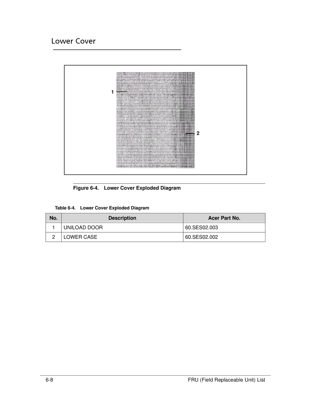
Lower Case
LCD Assembly
LCD BEZEL-52
Camera 1.3M
LCD Bracket R&L-52
Upper Cover
TP Button Board Mount W/ FFC Cable
Description Acer Part No
Lower Cover
Uniload Door
FRU List
FRU List
Blue Tooth CABLE-6PIN
DC-IN Cable
AC Clip US
AC Clip EU
HDD/HARD Disk Drive
LF F/WGJ002J
LCD
Antenna 3G-MAIN
Antenna 3G-AUX
Antenna WLAN-MAIN
Antenna WLAN-AUX
LCD CABLE-52 for W/O 3G
ANTENNA, CCD, Black Antenna WLAN-MAIN
LCD Cover IMR-52 Black for W/O 3G
LCD CABLE-36 for W/3G
ANTENNA, CCD, 3G-BLACK Antenna 3G-MAIN
LCD Cover IMR-36 Black for W/3G
LCD BEZEL-36
LCD Bracket R&L-36
LCD CABLE-36 for W/O 3G
LCD Cover IMR-36 Black for W/O 3G
MIC SET-52
MIC SET-36
Speaker L
HDD Mylar
MIC Mylar
LCD Screw PAD
FRU Screw List
Screw List
Screw 2D
FRU Field Replaceable Unit List
Model Definition and Configuration
AO522
AO522
RO & Description
ACLA-ES
AAP
AO522-C58kk LU.SES08.008
Ifrbf
AL/MK
SNW7ST32ERSSAL1 MC
SNW7ST32EMSSDZ1 MC
AO522-C5Dkk Baltic LU.SES0D.054
Gctwn
TWN
AO522-C5Dkk LU.SES0D.069
SNW7ST32EMSRME4 MC
SNW7ST32EMSRME2 MC
SNW7ST32EMSTME2 MC
SNW7ST32EMSTMEB MC
SNW7ST32EMSSME4 MC
SNW7ST32EMSSME6 MC
SNW7ST32EMSTME6 MC
SNW7ST32EMSTME4 MC
SNW7ST32EMSSME1 MC
SNW7ST32EMSRME9 MC
SNW7ST32EMSSME3 MC
SNW7ST32EMSTME9 MC
SNW7ST32RUSSRU1 MC
YU/BA
SNW7ST32ERSSBA1 MC
SI/HR
SNW7ST32EMSSZA2 MC
SNW7ST32EMSSTR1 MC
SNW7ST32EMSTTR1 MC
SNW7ST32EMSRTR1 MC
AMDC30B
BOM Name & CPU
AMDC50B
AO522-C5Ckk LU.SES0C.006 AO522UMACkk3
AO522-C5Dkk LU.SES0D.090 AO522UMACkk3
AO522-C5Dkk LU.SES0D.039 AO522UMACkk3
LCD & VGA Chip
NLED10.1WXGAG UMA
AO522-C5Dkk LU.SES0D.006
YU/BA
NLED10.1WSVGAGS UMA
Memory 1 & HDD
SO1GBIII10
SO2GBIII10
N320GB5.4KS AO522-C5Ckk LU.SES0C.003
N250GB5.4KS AO522-C5Dkk LU.SES0D.068
N250GB5.4KS AO522-C5Dkk LU.SES0D.036
Card Reader & Wireless LAN
LU.SES0D.005 1-Build 3rd WiFi 1x1 BGN AO522-C5Dkk
Card Reader & Wireless LAN
Bluetooth & NB Chipset
AMD A50M FCH
AL/MK
Gctwn
YU/BA
Battery, Adapter, & Camera
LU.SES0D.005 6CELL2.2 40W AO522-C5Dkk
Battery, Adapter, & Camera
LU.SES0D.018 6CELL2.2 40W AO522-C5Dkk
Model Definition and Configuration
Test Compatible Components
Microsoft Windows 7 Environment Test
Test Compatible Components
Microsoft Windows 7 Environment Test
AO522
SD, SC, XD
Digi
8MB LF F/WGJ002J
ML320S-AF Sata 8MB LF
NT0TA10B
NT0TA10W
NLED10.1WX LED LCD Samsung
GAG
Media Processor
Wireless LAN
Modem
NB Chipset
SB Chipset
Online Support Information
Introduction
Online Support Information
Online Support Information