Manuals
/
Acer
/
Computer Equipment
/
Laptop
Acer
5230, 5630Z SERIES
manual
Removing the SD dummy card
Models:
5230
5630Z SERIES
1
65
152
152
Download
152 pages
52.4 Kb
62
63
64
65
66
67
68
69
Troubleshooting
Specifications
Error messages
System Block Diagram
Bluetooth
Password
Euro symbol
Indicators
Intermittent Problems
Bios Setup Utility
Page 65
Image 65
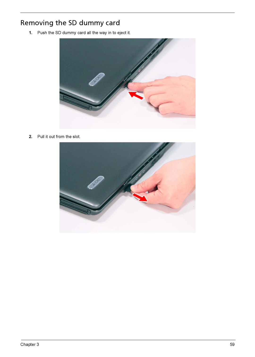
Removing the SD dummy card
1.
Push the SD dummy card all the way in to eject it.
2.
Pull it out from the slot.
Chapter 3
59
Page 64
Page 66
Page 65
Image 65
Page 64
Page 66
Contents
TravelMate Extensa 5230/5630Z Series Service Guide
Revision History
Copyright
Conventions
Preface
Page
Table of Contents
Jumper and Connector Locations
Microsoft Windows Vista Environment Test
Page
Chapter
Features
Ports
Cantiga/GL40
System Block Diagram
Front View
Your Acer Notebook tour
Icon Description
Closed Front View
Right View
Left View
Rear View
Bottom View
Easy-Launch Buttons
Indicators
Touchpad basics with two-click buttons
Touchpad Basics with fingerprint reader
Function Left button Right button Main touchpad
Lock Keys and embedded numeric keypad
Using the Keyboard
Fn + F11
F12
Ctrl + + TAB Use the arrow keys to
Windows Keys
Hot Keys
Special Key only for certain models
Euro symbol
Launching Acer Empowering Technology
Acer Empowering Technology
Click Create a new password
Empowering Technology password
Using power plans
Acer ePower Management
Acer eDataSecurity Management only for certain models
Acer eRecovery Management
Chapter
Acer eSettings Management
Windows Mobility Center
Using the System Utilities
Acer GridVista dual-display compatible
Chapter
Processor Specification
Hardware Specifications and Configurations
Processor
CPU Fan True Value Table
Memory Combinations
Hard Disk Drive Interface
Bluetooth Interface
Wireless Module 802.11b/g
Plds SUPER-MULTI Drive DL 8X DS-8A2S LF
Optical Disc Drive
System Board Major Chips
Audio Interface
Video Memory
LCD 15.4 inch
Battery
Keyboard
AC Adaptor
System Power Management
System Utilities
Bios Setup Utility
Navigating the Bios Utility
Parameter Description
Information
B M e n u F10 S a v e a n d E x i t
Main
Parameter Description Format/Option
F10 S a v e a n d E x i t
Security
Clear or Set
Setting a Password
Removing a Password
Page
I n C u r i t y O t I t
Boot
F o r m a t i o n I n C u r i t y O t I t
Exit
Bios Flash Utility
Remove HDD Password
Remove HDD/BIOS Utility
Remove Bios Password
Key in biospw 14452 Choose one upper-case string
Chapter
Disassembly Requirements
Machine Disassembly and Replacement
Disassembly Process
Pre-disassembly Instructions
General Information
Main Screw List
Screw List
External Module Disassembly Process
External Modules Disassembly Flowchart
Removing the Battery Pack
Removing the SD dummy card
Removing the PC and ExpressCard dummy cards
Removing the Lower Cover
Removing the Dimm
Removing the Wlan Board Modules
Detach the Wlan board from the Wlan socket
Removing the Hard Disk Drive Module
Removing the Optical Drive Module
Remove the one screw C from the bottom panel
M2 x L3 Silver Kgf-cm Chapter
Main Unit Disassembly Process
Removing the Middle Cover
Removing the Power Board
M2 x L3 Silver Kgf-cm
Removing the Keyboard
Removing the Heatsink Fan Module
Removing the CPU and VGA Heatsink Module
Removing the CPU
Removing the VGA Board Discrete Model only
Removing the LCD Module
M2.5 x L6 Black Kgf-cm
Separating the Upper Case from the Lower Case
Page
Chapter
~14 M2.5 x L5 Black Kgf-cm
Removing the Speaker Module
Removing the Launch Board
Removing the Fingerprint and Touchpad Module
Page
Remove the touchpad bracket
Removing the Modem Board
Lift the modem board from the system
Removing the USB Board Module
Removing the Main Board
Page
Remove the three screws B securing the main board in place
LCD Module Disassembly Process
Removing the LCD Bezel
Page
Removing the LCD module with the Brackets
Removing the FPC Cable
100 Chapter
Removing the LCD Brackets
Removing the Antennas
Removing the Web Camera
Remove the Web camera from the back cover
Symptoms Verified Go To
Troubleshooting
External Diskette Drive Check
System Check Procedures
External CD-ROM Drive Check
Keyboard or Auxiliary Input Device Check
Memory check
Power System Check
Check the Power Adapter
Touchpad Check
Check the Battery Pack
Power-On Self-Test Post Error Message
Error Message List Error Messages FRU/Action in Sequence
Index of Error Messages
Error Code List Error Codes Error Messages
CPU ID
Post
Code Beeps Post Routine Description
Phoenix Bios Beep Codes
Setup
116 Chapter
Code Beeps
118 Chapter
Power-Related Symptoms Symptom / Error Action in Sequence
Index of Symptom-to-FRU Error Message
LCD-Related Symptoms Symptom / Error Action in Sequence
Memory-Related Symptoms Symptom / Error Action in Sequence
PCMCIA-Related Symptoms Symptom / Error Action in Sequence
Speaker-Related Symptoms Symptom / Error Action in Sequence
Symptom / Error Action in Sequence
Page
Modem-Related Symptoms Symptom / Error Action in Sequence
Intermittent Problems
Undetermined Problems
Top and Bottom View
Jumper and Connector Locations
126 Chapter
Clearing Password Check
Clearing Password Check and Bios Recovery
Bios Recovery Boot Block
Bios Recovery by Crisis Disk
FRU Field Replaceable Unit List
TravelMate 5330 Series Exploded Diagram
Category Part Name and Description Acer Part No
TravelMate 5330 Series FRU List
Launch Board Cable
Lower Case W/MODEM CABLE&FAN
CPU Intel Celeronm T1600 1.66G
HDD 120GB 5400RPM Sata II Hgst
E89KS Norwegian Aspire Black Keyboard 1415KB-FV3 Black
Mainboard Mainboard HOMA2 Intel GL40
Extensa 5230/5630Z and TravelMate 5330 Series
Appendix a
Appendix B
Test Compatible Components
Microsoft Windows Vista Environment Test
Specification CRT Port Test
Appendix B 141
142
Appendix C
Online Support Information
144
Index
146
Top
Page
Image
Contents