Manuals
/
Acer
/
Computer Equipment
/
Laptop
Acer
9520, 6500, 9510
manual
Remove the CPU as shown Remove the TV cable
Models:
9520
9510
6500
1
82
131
131
Download
131 pages
48.22 Kb
79
80
81
82
83
84
85
86
Troubleshooting
Specs
Dynamic Output Characteristics
Error codes
Block Diagram
Password
Default Application
Euro Symbol
Indicators
Dimension
Page 82
Image 82
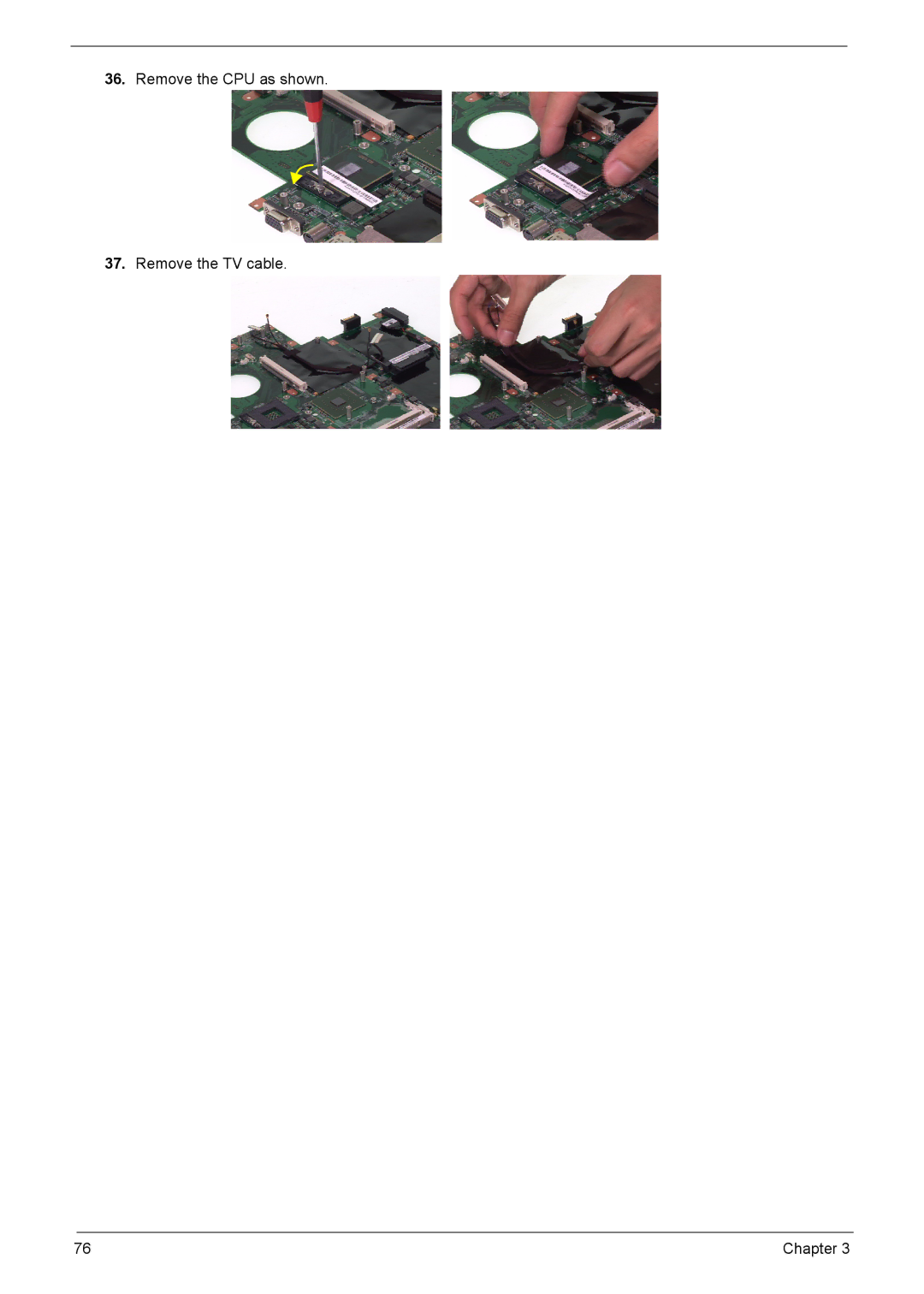
36.
Remove the CPU as shown.
37.
Remove the TV cable.
76
Chapter 3
Page 81
Page 83
Page 82
Image 82
Page 81
Page 83
Contents
Service Guide
TravelMate6500&Aspire9510/9520
Revision History
Copyright
Disclaimer
Conventions
Screen messages
Preface
System Utilities
Features
Chapter
Storage subsystem
Communication
Ports
Power Supply
Dimensions and weight
Environment
Kirkini Block Diagram Revision
Block Diagram
Front Open View
Aspire 9510 Outlook View
Icon Description
Closed Front View
Left View
Right View
Rear View
DVI-D
Bottom View
TravelMate 6500 Outlook View
Close Front View
Left View
Base View
Chapter
Indicators
Default Application
Easy-Launch Buttons
Touchpad
Touchpad Basics
Lock keys and Embedded Numeric Keypad
Using the Keyboard
Desired access Num Lock on Num Lock off
Lock Key Description
Windows Keys
Hotkeys
Hot Key Icon Description
Special Keys
Euro Symbol
US Dollar Sign
Using the System Utilities
Acer GridVistadual-display compatible
Norton AntiVirus
Launch Manager
How do I check for viruses?
Scan for Viruses panel, click Scan My Computer
Empowering Technology Password
Acer Empowering Technology
Acer eNet Management
Chapter
DC Mode Battery mode
Acer ePower Management
AC Mode Adapter mode
To create new power profile
Battery status
Acer ePresentation Management
Acer eDataSecurity Management
Acer eLock Management
Acer eRecovery Management
Acer eSettings Management
Acer ePerformance Management
Acer OrbiCam
Rotating the Acer OrbiCam
Getting to know your Acer OrbiCam
Launching the Acer OrbiCam
Changing the Acer OrbiCam settings
Camera Settings
Capturing photos or videos
Using the Acer OrbiCam as webcam
To enable the Acer VisageON
Enabling the Acer VisageON
Using the face tracking feature
Using video effects selected models only
Stage DTSdegree C Local Fan Speedrpm Acoustic LeveldBA
Hardware Specifications and Configurations
Specification
Controller
System Memory
Discrete
USB Port
Battery
Package configuration
Dynamic Output Characteristics
Output Ratings CV mode
Input Requirements
OVP
Dielectric Withstand Voltage
24X Combo Drive Interface
Philips SCB5265 Liteon SSC-2485K
DVD-R 4.7G, DVD-RW, DVD+R
8X Super Multi Interface
Acpi Mode Power Management
Details Model Aspire
Environmental Requirements
Bios Setup Utility
Function
Information
Parameter Description
Advanced Security Boot Exit
Main
F12 Boot Menu
Security Boot Exit
Advanced
Security
Parameter Description Option
Disabled
Set Supervisor/User Password
Enter
Setup Notice Changes have been saved Continue
Boot
PCI Scsi
Info Main Security Boot
Exit
Machine Disassembly and Replacement
Disassembly Procedure Flowchart
General Information
Before You Begin
Removing the Battery Pack
Main Unit Disassembly
Removing the Wireless Card and Memory
Removing the HDD
Removing the TV Card
Separate the LCD Module
Chapter
Separate the Upper and Lower Case
Disassemble the Upper Case
Disassemble the Lower Case
Chapter
Page
Page
Remove the CPU as shown Remove the TV cable
LCD Disassembly
Chapter
CCD Module Disassembly
HDD Disassembly
ODD Disassembly
Troubleshooting
External CD-ROM Drive Check
System Check Procedures
External Diskette Drive Check
Keyboard or Auxiliary Input Device Check
Power System Check
Check the Battery Pack
Touchpad check
Power-On Self-Test Post Error Message
Index of Error Messages
Error Message List
No beep Error Messages FRU/Action in Sequence
Phoenix Bios Beep Codes
Code Beeps Post Routine Description
Chapter
Code Beeps Post Routine Description
Following are for boot block in Flash ROM
Indicator-Related Symptoms
Index of Symptom-to-FRU Error Message
LCD-Related Symptoms
Power-Related Symptoms
Speaker-Related Symptoms
PCMCIA-Related Symptoms
Memory-Related Symptoms
Power Management-Related Symptoms
Peripheral-Related Symptoms
Keyboard/Touchpad-Related Symptoms
Modem/LAN-Related Symptoms
Intermittent Problems
Undetermined Problems
Dimm
Jumper and Connector Locations
Mainboard Layout
Switching Setting
PH at ICH6M
Clear Password
FRU Field Replaceable Unit List
Exploded Diagram
CCD PCB
Chapter 104
Spare Part List
Adapter
Chapter 106
CASE/COVER/BRACKET Assembly
Chapter 108
FAN
Chapter 110
Keyboard
Chapter 112
Camera Lower Case Assy Camera Lcase
Chapter 114
Category Part Name Description OEM Part No
Chapter 116
CASE/COVER Optical Bracket Brktoddbrzcketkirkini
Chapter 118
Drive 7200RPM Sata
Chapter 120
CASE/COVER Camera Holder CAP Hldrcameracapkirkini
Chapter 122
Communication Wireless Antenna Antenna Cable MYALL2
Chapter 124
125 Chapter
Top
Page
Image
Contents