Manuals
/
Acer
/
Computer Equipment
/
Computer Monitor
Acer
AL1912
manual
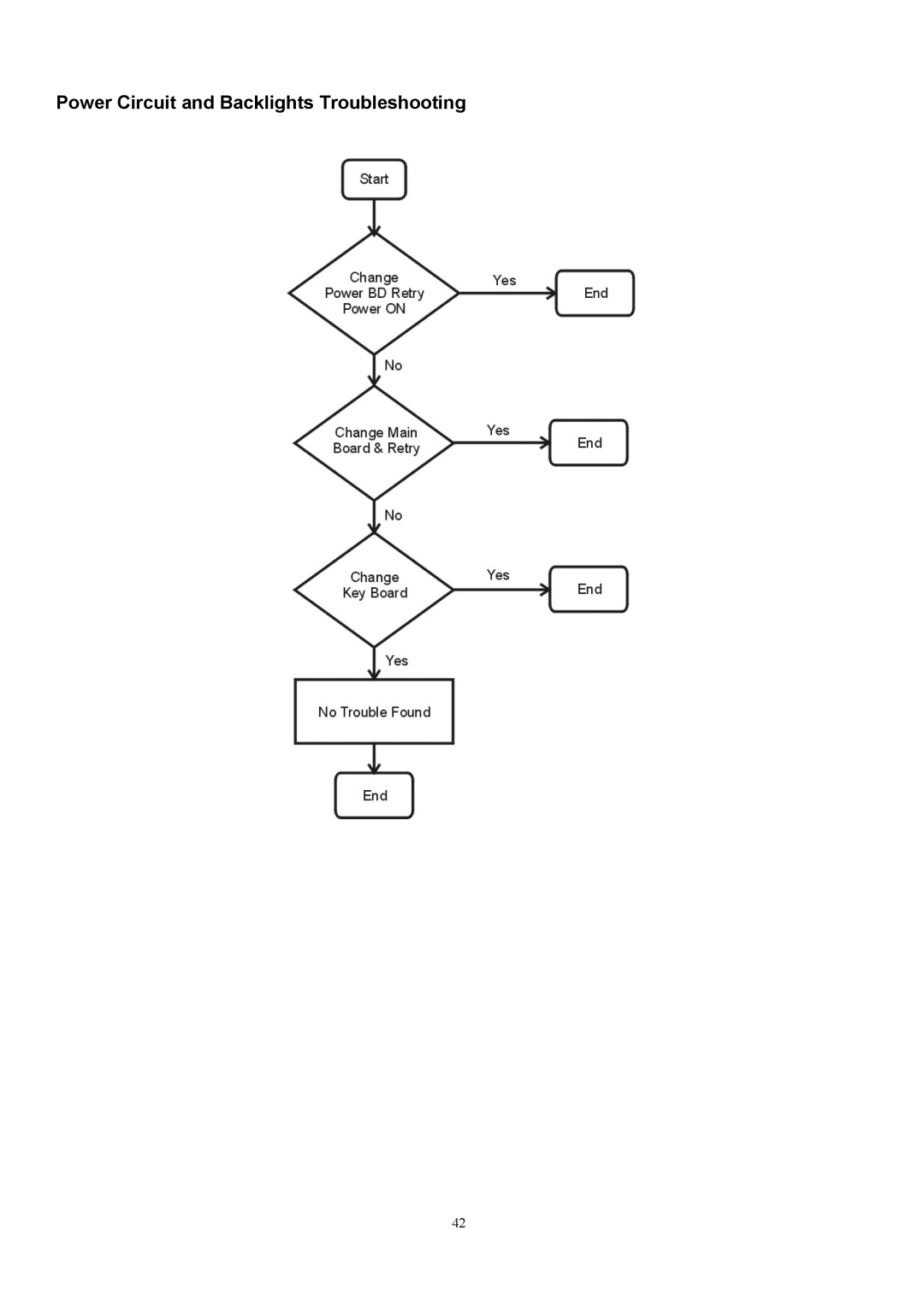
Power Circuit and Backlights Troubleshooting
Models:
AL1912
1
42
62
62
Download
62 pages
31.4 Kb
39
40
41
42
43
44
45
46
Troubleshooting
Specification
Install
Monitor Block Diagram
Interface Signals
Video input Connector
Disassembly Procedure
White Color Temperature
Precautions
Safety
Page 42
Image 42
Power Circuit and Backlights Troubleshooting
42
Page 41
Page 43
Page 42
Image 42
Page 41
Page 43
Contents
Acer AL1912 Service Guide
Copyright
Disclaimer
Conventions
Preface
Page
Precautions
Special Notes on LCD Monitors
Table of contents
Comparison Chart of AL1912 m/AL1912
Introduction
Scope
Measuring Equipment Control settings
Electrical Requirements
Standard Test Conditions
LCD monitor General specification
LCD Panel Specification
Total output power60 Watt max
LCD Panel Model Hydis LT17E12-200
Sync input
Panel Relative Humidity Input Signals
Video input
Interface frequency
Supported Timing
Apple MAC-480
Support Modes
Video input Connector
Analog Video input Connector 15pins mini D-Sub
85Hz refresh rate Support
Monitor Block Diagram
Block Diagram
System Block Diagram
Monitor board layout
Software flow chart
General Instructions
External Controls
Connecting the AC Power
System Installation
Connecting the Display
Connecting the Audio Cable For AL1912 m and AL1912 bm
Page
Page
LCD Horizontally
Plastic Material
GAP Spec
Tilt Base Rotation
For TCO99
POWER/Inverter Board
Interface Signals
Electrical Specification
AC-DC Electrical specification
Input Specification Condition Min Typ Max Unit
AC-DC Output Specification
Protection function
Inverter Electrical Specification
Safety
For Fujitsu FLC488SC8V-10 AL1912 m
Connectors
Power Consumption
Connectors / Controls
Monitor Control Keys
Controls
Control panel monitor front panel
Main OSD Menu
Outline Description for control function
简体中文
OSD Message
Operation Icon Description Adjustment Reset Range Value
Hot-Key MenuFor AL1912 m only
Outline Description for Hot-Key function
Bright
Logo
Item of Factory menu
Auto Balance
Plug & play DDC2B feature
Using The Right Power Cord
Plug and play
White Color Temperature
Audio Technical specification For AL1912 m only
General Description
Electrical characteristics Tamb=25
Speakers
Audio amplifierUSE Panasonic VP-7723A Audio Analyzor
Disassembly Procedure
Disassemble the base
Disassemble the chassis
Disassemble the power board
Disassemble the main board
Disassemble the key board
Disassemble the speakers
Troubleshooting
Main Procedure
Power Circuit and Backlights Troubleshooting
Performance Troubleshooting
Function Troubleshooting
Connector Information
Phonejack stereo
FRU Field Replaceable Unit list
Model AL1912
ModelAL1912 m
Part list Photo Part Name
LCD R
Page
Schematic Diagram
Page
Page
Page
Page
Page
Page
Page
Page
Top
Page
Image
Contents