Manuals
/
Acer
/
Computer Equipment
/
Computer Monitor
Acer
B243W
manual
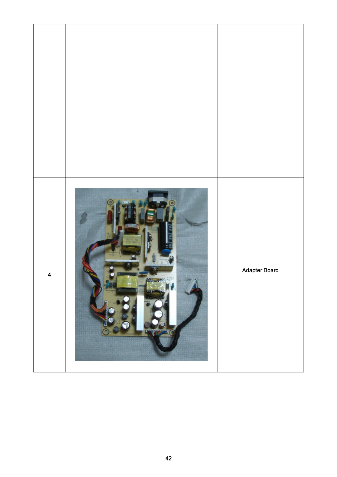
Adapter Board
Models:
B243W
1
42
56
56
Download
56 pages
41.06 Kb
39
40
41
42
43
44
45
46
Troubleshooting
Specification
Electrical Characteristics
Install
Chart of B243W
Symbol
EEPROM/Config
Connector Information
Machine Disassembly
Screen Position Adjustment
Page 42
Image 42
Page 41
Page 43
Page 42
Image 42
Page 41
Page 43
Contents
Acer B243W Service Guide
Release Date
Service Guide Version and Revision
Version
Revision History
Trademarks
Copyright
Disclaimer
Conventions
Preface
Warning For FCC Certified Models
Precautions
Special Notes On LCD Monitors
Table Of Contents
Chapter
Monitor Features
Chart of B243W
Introduction
Electrical Requirements
Standard Test Conditions
LCD Monitor General Specification
LCD Panel Specification
General Specifications
Mechanical Information
Electrical Characteristics
Optical Specifications
Support Timing VESA MODES
Horizontal
Vertical
Monitor Block Diagram
Main Board Diagram
Crystal
Software Flow Chart
Remark
Main Board Layout
Symbol
Installation
Screen Position Adjustment
Height Adjustment
Attaching/Removing The Base
Tilt
Swivel
Monitor Pivot
Operating Instructions
External Controls
Front panel controls
eColor Management OSD
How to Adjust a Setting
Adjusting the picture
Page
Logo
How To Optimize The DOS-Mode Plug And Play Plug & Play DDC2B Feature
Using The Right Power Cord
Machine Disassembly
Disassembly Procedure
3. Release the shield inverter and lamp connectors. Fig
Page
Page
Troubleshooting
This chapter provides troubleshooting information for the B243W
1. No Power
2. No Picture LED is orange
3. White screen
Connect Key Board Replace Button Switch Replace Key Board
4. Key Board
Is Key Pad Board connecting normally? Y NG Is Button Switch normally?
OSD is unstable or not working NG
5. Adapter/Inverter Board No power
W/LED No Backlight
Connector Information
The following figure shows the connector locations on the monitor
D-SUB connector
DVI Connector
Exploded Diagram Model B243W
Chapter
FRU Field Replaceable Unit List
Part List
Picture
Adapter Board
Inverter Board Main Board USB Board
LVDS Cable
POWER INPUT
Schematic Diagram
Main Board
FOR SCALER POWER
CONNECTION
DVICONNECTMCU
CABLE
CABLE NOT
MST9200A-LF
REVC
1M X 16bit =512K X 2Bank
AUDIO
For HDCP
AUDIOMUTE
AUDIOSTDBY HI
CN703
CONNECT
LVDS INTERFACE
CONN
T5A 250VAC
Adapter board
ON/OFF
PSON
In SVT Add it
THE PIN ADDED FERRITE BEAD THE SOLUTION FOR EMI
400V
Improve EMI
Inverter board
OVP Over Voltage Protation
Q810
C829
POWERKey
CONNECTOR
POWER
POWER Key
Power Regulator
Power
EEPROM/Config
Upstream
Top
Page
Image
Contents