slot,andthenremovethe slot cover (refer to Fig- ure
4.Carefully slide the in- ternal modem into the slot you have chosen, applying even pressure until the modem is com- pletely seated in the slot.
5.Fasten the retaining
bracket with the screw from the slot cover.
Make sure the modem is properly aligned. Store the slot cover for future use.
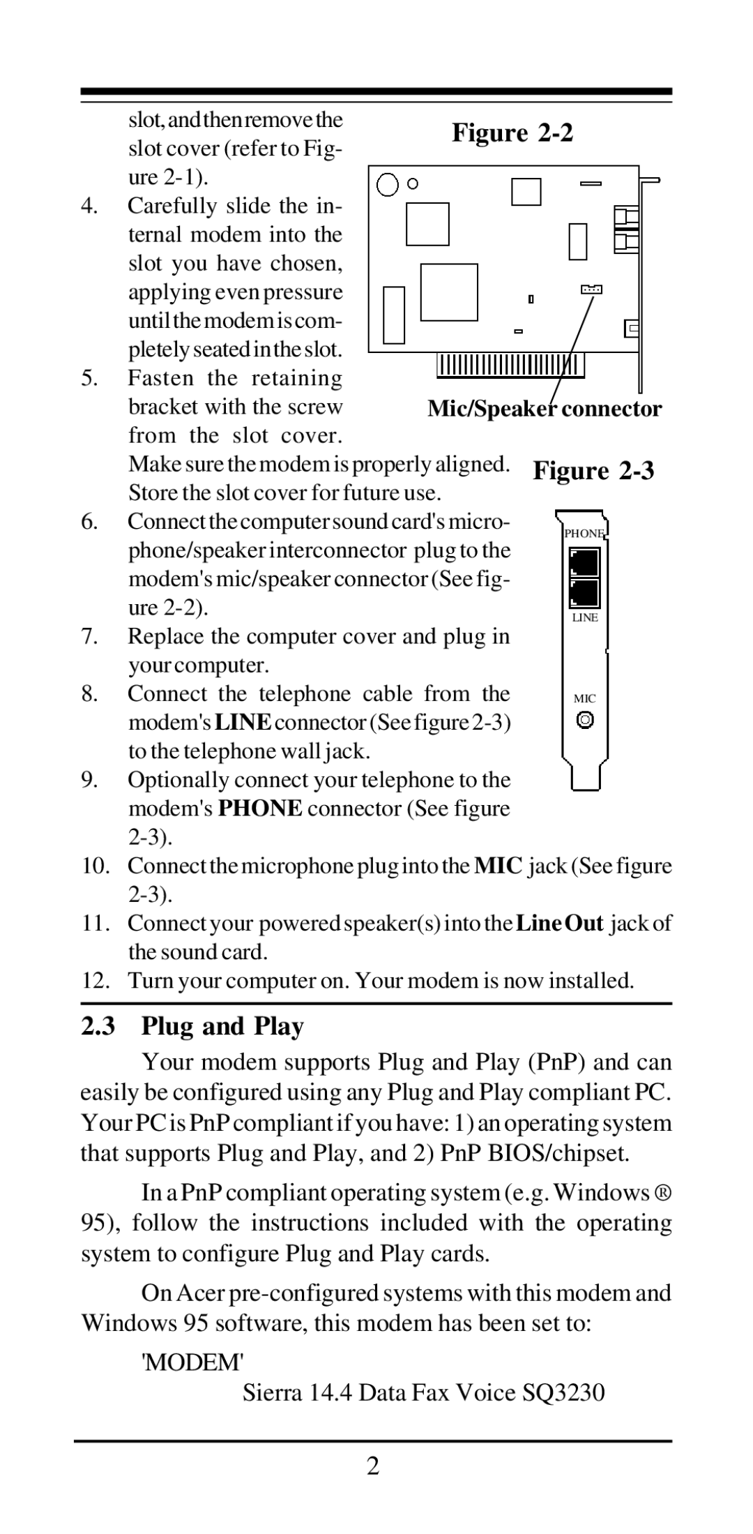
6.Connect the computer sound card's micro-
phone/speaker interconnector plug to the modem's mic/speaker connector (See fig- ure
7.Replace the computer cover and plug in your computer.
8. Connect the telephone cable from the modem'sLINE connector (See figure
9.Optionally connect your telephone to the modem'sPHONE connector (See figure
10.Connect the microphone plug into the MIC jack (See figure
11.Connect your powered speaker(s) into the Line Out jack of the sound card.
12.Turn your computer on. Your modem is now installed.
2.3 Plug and Play
Your modem supports Plug and Play (PnP) and can easily be configured using any Plug and Play compliant PC. Your PC is PnP compliant if you have: 1) an operating system that supports Plug and Play, and 2) PnP BIOS/chipset.
In a PnP compliant operating system (e.g. Windows ® 95), follow the instructions included with the operating system to configure Plug and Play cards.
On Acer
'MODEM'
Sierra 14.4 Data Fax Voice SQ3230
2
