Manuals
/
Acer
/
Computer Equipment
/
Laptop
Acer
X5812, X3812
manual
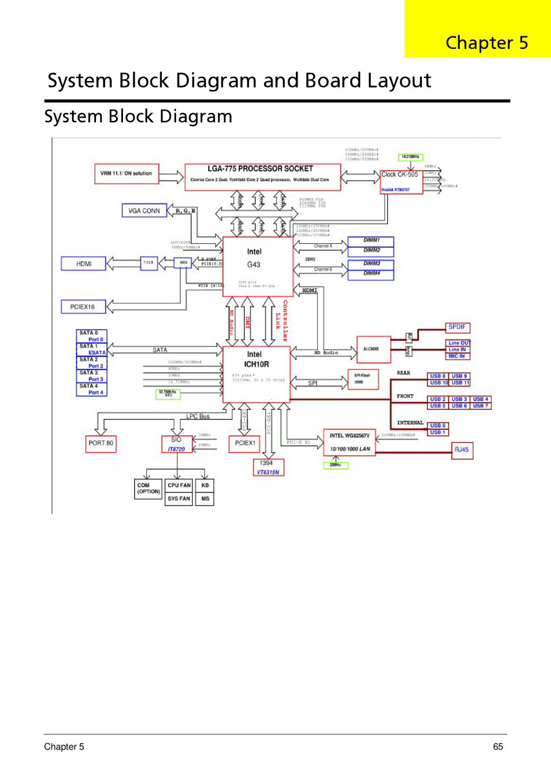
System Block Diagram and Board Layout
Models:
X5812
X3812
1
73
108
108
Download
108 pages
36.49 Kb
70
71
72
73
74
75
76
77
Troubleshooting
Specs
Error messages
System Block Diagram
Password
Load Default Settings
System LED Indicators
Dimension
System Configuration
Cmos Setup Utility
Page 73
Image 73
Chapter 5
System Block Diagram and Board Layout
System Block Diagram
Chapter 5
65
Page 72
Page 74
Page 73
Image 73
Page 72
Page 74
Contents
Acer Aspire X3812/X5812 Service Guide
Revision History
Copyright
Disclaimer
Conventions
Service Guide Coverage
Table of Contents
Chapter System Block Diagram and Board Layout
Chapter
Features
Power supply
System Bios
Ports
Operating system and software
Dimension and weight
Front Panel
System Components
X3812
Icon Component
X5812
Rear Panel
Internal Components
LED indicator Color LED status Description
System LED Indicators
System Utilities
Cmos Setup Utility
Navigating Through the Setup Utility
Entering Cmos setup
Setup Utility Menus
Parameter Description
Product Information
Parameter Description Option
Standard Cmos Features
Enabled
Advanced Bios Features
Auto
Advanced Chipset Features
Ahci
Integrated Peripherals
Power Management Setup
PC Health Status
Frequency/Voltage Control
Setting a system password
Bios Security Features
Removing a system password
Load Default Settings
Save & Exit Setup
Exit Without Saving
Bios Recovery
Chapter
Disassembly Requirements
System Disassembly
Pre-disassembly Procedure
Main Unit Disassembly
Main Unit Disassembly
Removing the Side Panel
Removing the Front Bezel
Removing the Heat Sink Fan Assembly
Removing the Processor
Removing the Optical Drive
Page
Remove the two screws B from the optical drive
Removing the Hard Disk Drive
Removing the Power Supply
Lift the power supply module out of the chassis Chapter
Removing the Memory Modules
Removing the TV Tuner Card
Removing the VGA Card
Disconnect the VGA card cable from the mainboard Chapter
Removing the Front I/O and Card Reader Boards
Remove the screw D that secures the bracket to the chassis
Pull the I/O board out of the bracket
Removing the Mainboard
Remove the screw B on the rear panel
Hardware Diagnostic Procedure
System Troubleshooting
Power System Check
System Check Procedures
System External Inspection
System Internal Inspection
Bootblock Initialization Code Checkpoints
Viewing Bios checkpoints
Checkpoints
Checkpoint Description
Bootblock Recovery Code Checkpoints
Post Code Checkpoints
Initialize RTC date/time
High Byte XY
DIM Code Checkpoints
Post Bios Beep Codes
Boot Block Beep Codes
Beep Symptom Cause and Description
Beep Codes
Troubleshooting Post Bios Beep Codes
Boot
Error Messages
Memory
Message Displayed Description
Storage Device
Virus Related
Eprom
System Configuration
Miscellaneous
Cmos
Smbios eModule Error Messages
USB eModule Error Messages
CPU eModule Error Messages
MPS Table Multi-processor eModule Error Messages
Online Support Information
System Block Diagram
System Block Diagram and Board Layout
Mainboard
Board Layout
Code Description
PWR2
System Jumper
Name Location Default Settings
FRU Field Replaceable Unit List
Aspire X3812/X5812 Exploded Diagram
Part Name
Category Part Name Acer Part Number
X3812 FRU List
Modem Card LITE-ON D-1156E#A10A LOW-PROFILE PCI-E 56K
Lower Case
HDD 1TB 3.5 7200RPM Sata Hgst Saturn HDT721010SLA360
Keyboard PS2 104KEY Chicony KB-07593S32552V Russian Black
Keyboard PS2 105KEY LITE-ON SK-9620 SG-30600-35W Swedish
Keyboard USB 105KEY Chicony KU-07606CH2552V SWISS/G Black
Keyboard USB 105KS LITE-ON SK-9625 Black Belgium
Pointing Device Mouse PS2 OPT SM-9620 Liteon SM-30600-00W
X5812 FRU List
CASE/COVER/BRACKET Assembly Front Bezel
Upper Case
Keyboard
Keyboard PS2 104KEY Chicony KB-07593US2552V US2552V US Blac
Keyboard PS2 104KEY Chicony KB-07593S32552V Russian Black
Keyboard PS2 105KEY LITE-ON SK-9620 SG-30600-35W Swedish
Keyboard USB 105KEY Chicony KU-07606CH2552V SWISS/G Black
Memory Memory Nanya DDR3 1333MHZ 1G NT1GC64B88A0NF-CG
Rohs Power Supply 220W PFC 230V Liteon PE-5221-08AP-ROHS
Chapter
Chapter
Intel Core 2 Duo Specification
Intel Core 2 Quad Specification
Appendix a
Intel Celeron Dual-Core Specification
Intel Pentium Dual-Core Specification
System Memory
Hard Disk Drive
Network Interface Specification
Audio Interface
Super Multi Specification
RW 8X CLV
DVD-ROM
Appendix a 100
Top
Page
Image
Contents