Manuals
/
Acnodes
/
Household Appliance
/
Heat Pump
Acnodes
Q5RF SERIES User Information, Installer Information, Refrigerant Charging Charts for
Models:
Q5RF SERIES
1
2
20
20
Download
20 pages
62.72 Kb
1
2
3
4
5
6
7
8
Install
Q5RF-X24KCHARGING CHART
Anti Short Cycle Timer Test
Maintenance
Accessory
60HZ/SINGLE PHASE
Checklist
Safety
High Pressure Switch
Page 2
Image 2
Page 1
Page 3
Page 2
Image 2
Page 1
Page 3
Contents
Q5RF SERIES
DO NOT DESTROY. PLEASE READ CAREFULLY AND
KEEP IN A SAFE PLACE FOR FUTURE REFERENCE
Single Package Heat Pump - 2 Stage, R-410A
Refrigerant Charging Charts for
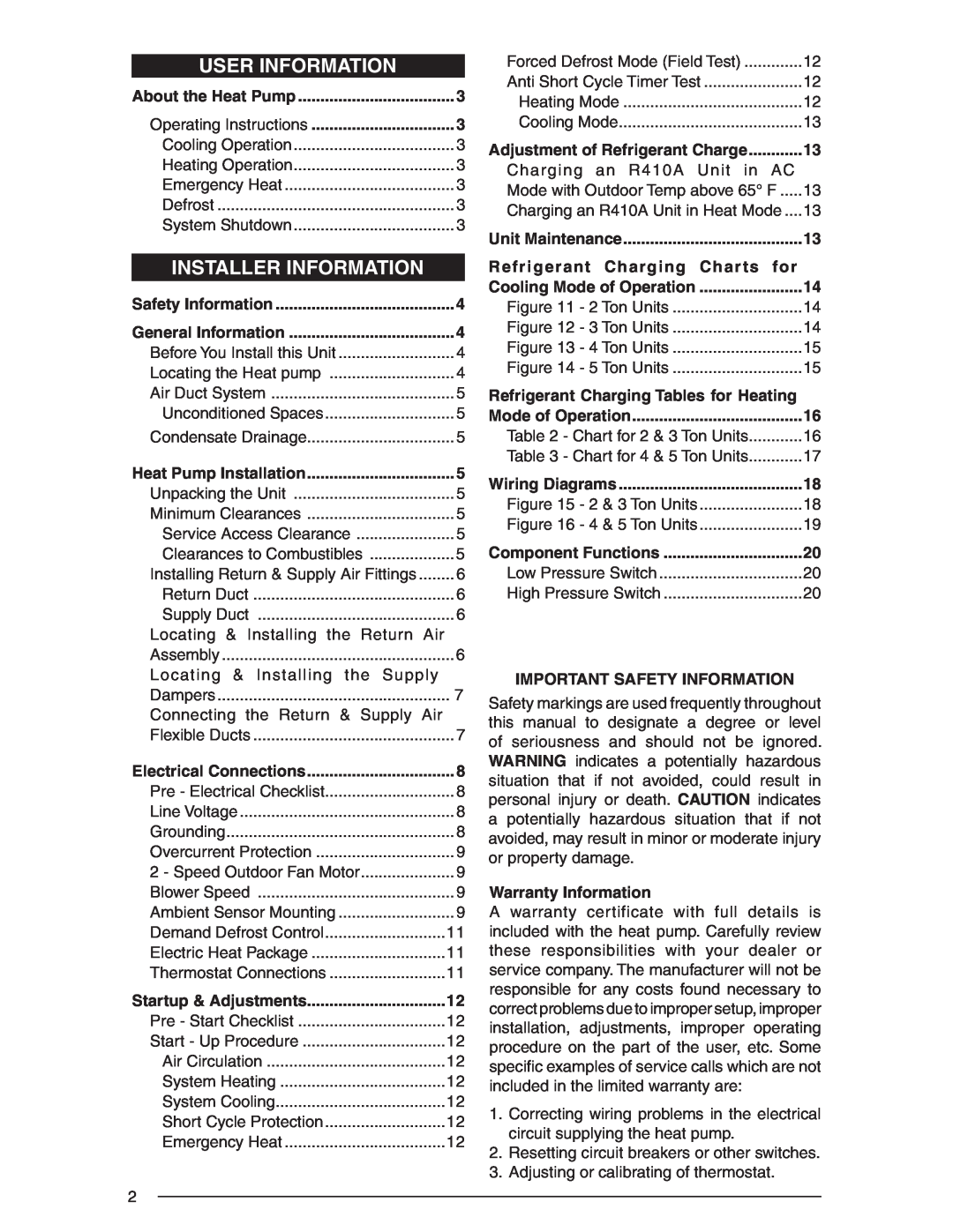
INSTALLER INFORMATION
USER INFORMATION
IMPORTANT SAFETY INFORMATION
Operating Instructions
USER INFORMATION
ABOUT THE HEAT PUMP
Figure 1. Digital Thermostat
Before You Install this Unit
INSTALLER INFORMATION
SAFETY INFORMATION
GENERAL INFORMATION
Condensate Drainage
Figure 2. Drain Trap HEAT PUMP INSTALLATION
Air Duct System
Elbow
Make sure the filter is readily accessible
Installing Return & Supply Air Fittings
Locating & Installing the Return Air Assembly
Figure 3. Minimum Unit Clearances
Figure 7. Supply Damper
Locating & Installing the Supply Dampers
Figure 6. Return Air Box
ELECTRICAL CONNECTIONS
Pre-ElectricalChecklist
Figure 8. Power Entry
Line Voltage
Blower Speed
Overcurrent Protection
2-SpeedOutdoor Fan Motor Select Models
Ambient Sensor Mounting
Minimum Time
Demand Defrost Control
Jumper
Terminate
INDOOR THERMOSTAT
Accessory
Accessory
SUB-BASE
Anti Short Cycle Timer Test
STARTUP & ADJUSTMENTS Pre-StartChecklist
Start-UpProcedure
Forced Defrost Mode Field Test
Charging an R-410AUnit in Heating Mode
Adjustment of Refrigerant Charge
UNIT MAINTENANCE
Figure 12. Charging Chart for 3 ton Units
Refrigerant Charging Charts for
Figure 11. Charging Chart for 2 ton Units
Q5RF-X24KCHARGING CHART
Figure 14. Charging Chart for 5 ton Units
Refrigerant Charging Charts for
Figure 13. Charging Chart for 4 ton Units
Q5RF-X48KCHARGING CHART
Shaded boxes indicate flooded conditions
Q5RF-X48K
Q5RF-X60KK
¢711065«¤
WIRING DIAGRAM
60HZ/SINGLE PHASE
208/230V
¢711066#¤
WIRING DIAGRAM
60HZ/SINGLE PHASE
208/230V
¢709158D¤
COMPONENT FUNCTIONS Low Pressure Switch
High Pressure Switch
Model Q5RF
Top
Page
Image
Contents