ADCP-61-743 Issue 3 September 2004

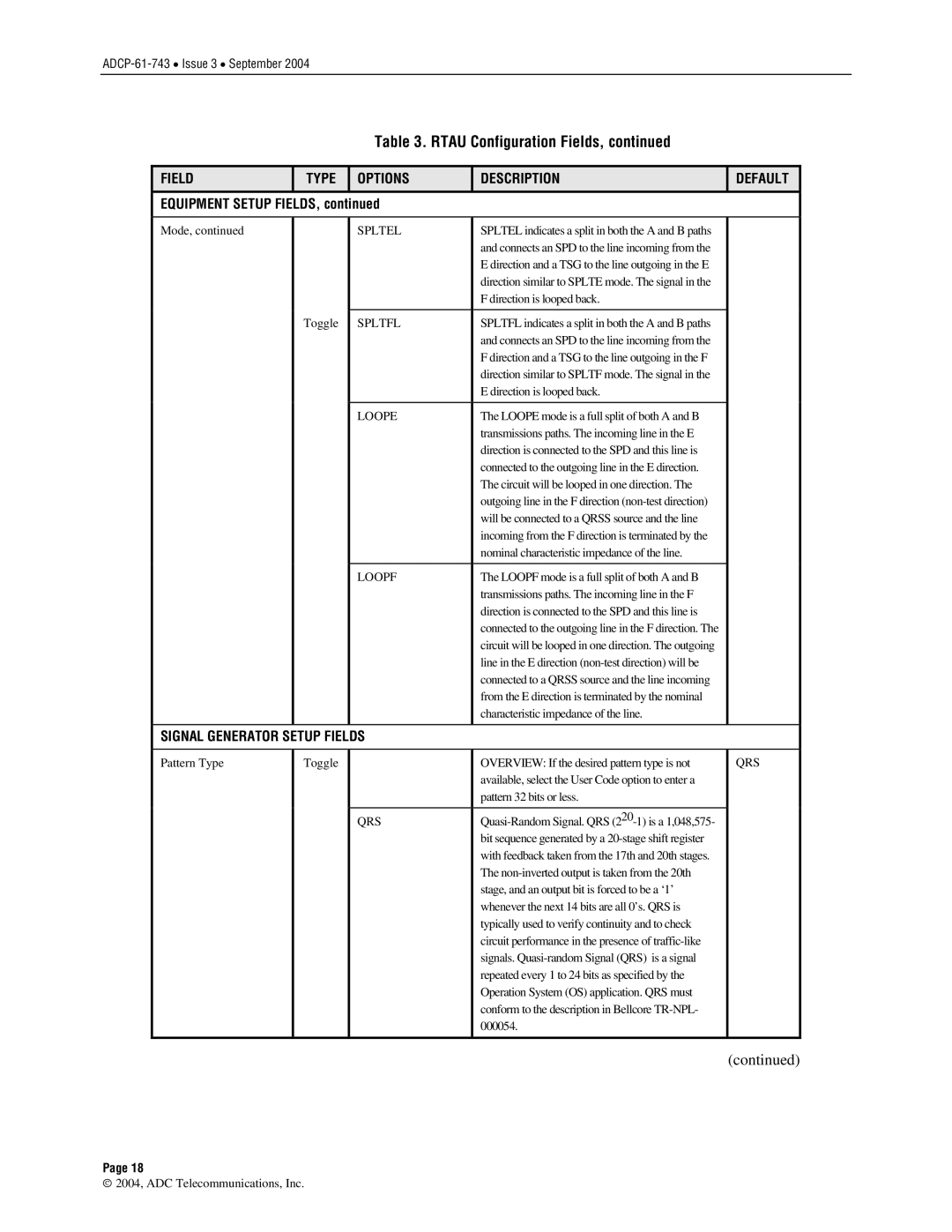
Table 3. RTAU Configuration Fields, continued

FIELD

TYPE

OPTIONS

DESCRIPTION

DEFAULT

EQUIPMENT SETUP FIELDS, continued


Mode, continued


SPLTEL

SPLTEL indicates a split in both the A and B paths


and connects an SPD to the line incoming from the


E direction and a TSG to the line outgoing in the E


direction similar to SPLTE mode. The signal in the


F direction is looped back.


Toggle

SPLTFL

SPLTFL indicates a split in both the A and B paths


and connects an SPD to the line incoming from the


F direction and a TSG to the line outgoing in the F


direction similar to SPLTF mode. The signal in the


E direction is looped back.


LOOPE

The LOOPE mode is a full split of both A and B


transmissions paths. The incoming line in the E


direction is connected to the SPD and this line is


connected to the outgoing line in the E direction.


The circuit will be looped in one direction. The


outgoing line in the F direction (non-test direction)


will be connected to a QRSS source and the line


incoming from the F direction is terminated by the


nominal characteristic impedance of the line.


LOOPF

The LOOPF mode is a full split of both A and B


transmissions paths. The incoming line in the F


direction is connected to the SPD and this line is


connected to the outgoing line in the F direction. The


circuit will be looped in one direction. The outgoing


line in the E direction (non-test direction) will be


connected to a QRSS source and the line incoming


from the E direction is terminated by the nominal


characteristic impedance of the line.


SIGNAL GENERATOR SETUP FIELDS


Pattern Type

Toggle


OVERVIEW: If the desired pattern type is not

QRS


available, select the User Code option to enter a


pattern 32 bits or less.


QRS

Quasi-Random Signal. QRS (220-1) is a 1,048,575-


bit sequence generated by a 20-stage shift register


with feedback taken from the 17th and 20th stages.


The non-inverted output is taken from the 20th


stage, and an output bit is forced to be a ‘1’


whenever the next 14 bits are all 0’s. QRS is


typically used to verify continuity and to check


circuit performance in the presence of traffic-like


signals. Quasi-random Signal (QRS) is a signal


repeated every 1 to 24 bits as specified by the


Operation System (OS) application. QRS must


conform to the description in Bellcore TR-NPL-


000054.


(continued)

Page 18

2004, ADC Telecommunications, Inc.

Page 18
Image 18
ADC P-61-743 user manual Spltel, Spltfl, Loope, Loopf, Qrs

P-61-743 specifications

The ADC P-61-743 is a sophisticated air defense communication system designed to enhance the situational awareness and operational effectiveness of military units. This compact yet powerful system integrates advanced technologies, offering superior performance in a variety of challenging environments. One of the hallmark features of the P-61-743 is its robust data processing capabilities, allowing for real-time analysis and interpretation of incoming threats. By utilizing cutting-edge processing algorithms, the system can quickly filter and prioritize threats, ensuring that personnel can respond effectively and efficiently.

Equipped with a multi-functional user interface, the P-61-743 provides operators with intuitive control and monitoring capabilities. This interface displays critical information, including threat identification, tracking data, and communication statuses, in an easily digestible format. Additionally, the system's modular design allows for seamless upgrades and integrations, making it adaptable to rapidly changing technological landscapes and mission requirements.

The P-61-743 employs advanced communication technologies, facilitating secure and encrypted data exchanges across multiple platforms. This ensures that vital information remains confidential and protected against interception or unauthorized access. Moreover, the system supports interoperability with various existing military communication networks, promoting cohesive operation among allied forces.

Another notable characteristic of the P-61-743 is its resilience to electronic warfare. It features sophisticated countermeasure systems that provide protection against jamming and spoofing attempts, ensuring that critical communications remain intact even in contested environments. The system's architectural design enables it to function effectively in diverse terrains, from urban centers to remote military bases, showcasing its versatility.

The ADC P-61-743 is not only focused on immediate defense needs but also incorporates artificial intelligence-driven predictive analytics. By analyzing historical data and current conditions, the system can forecast potential threats and recommend preemptive actions, thus enhancing the overall strategic advantage of military units.

In summary, the ADC P-61-743 is a state-of-the-art air defense communication system characterized by its advanced data processing, user-friendly interface, robust communications technology, electronic warfare resilience, and predictive analytics capabilities. These features make it an invaluable asset in modern military operations, ensuring that forces remain prepared and responsive in an increasingly complex threat landscape.