Host computer connections
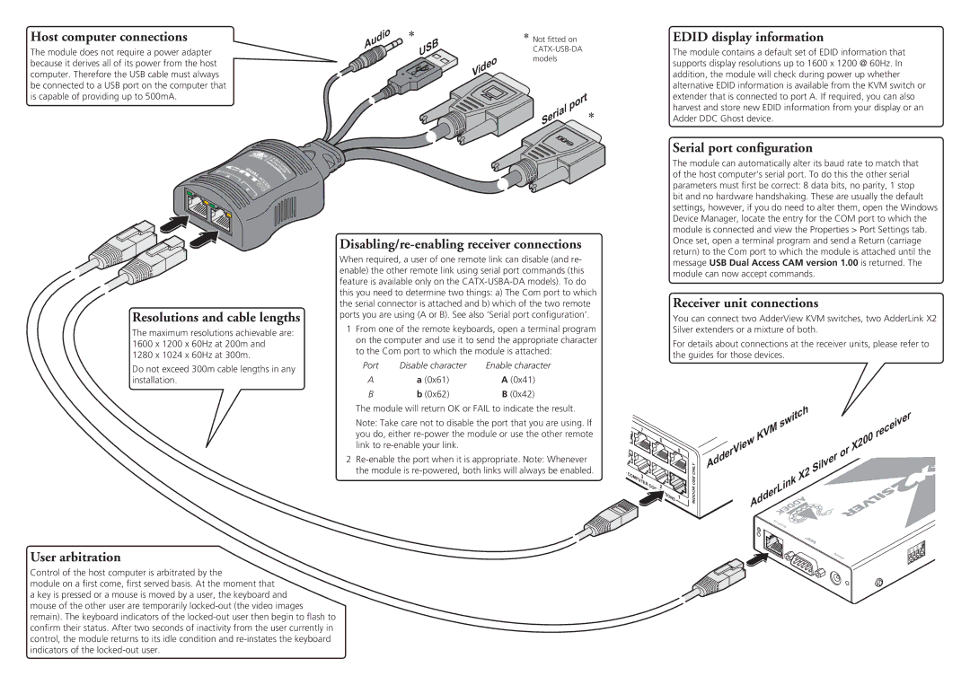
The module does not require a power adapter because it derives all of its power from the host computer. Therefore the USB cable must always be connected to a USB port on the computer that is capable of providing up to 500mA.
Audio![]()
![]()
*
USB
*Not fitted on
Video
| port | * |
Serial |
|
EDID display information
The module contains a default set of EDID information that supports display resolutions up to 1600 x 1200 @ 60Hz. In addition, the module will check during power up whether alternative EDID information is available from the KVM switch or extender that is connected to port A. If required, you can also harvest and store new EDID information from your display or an Adder DDC Ghost device.
Serial port configuration
Resolutions and cable lengths
The maximum resolutions achievable are: 1600 x 1200 x 60Hz at 200m and 1280 x 1024 x 60Hz at 300m.
Do not exceed 300m cable lengths in any installation.
Disabling/re-enabling receiver connections
When required, a user of one remote link can disable (and re- enable) the other remote link using serial port commands (this feature is available only on the
1From one of the remote keyboards, open a terminal program on the computer and use it to send the appropriate character to the Com port to which the module is attached:
Port | Disable character | Enable character |
A | a (0x61) | A (0x41) |
B | b (0x62) | B (0x42) |
The module will return OK or FAIL to indicate the result.
Note: Take care not to disable the port that you are using. If you do, either
2
The module can automatically alter its baud rate to match that of the host computer’s serial port. To do this the other serial parameters must first be correct: 8 data bits, no parity, 1 stop bit and no hardware handshaking. These are usually the default settings, however, if you do need to alter them, open the Windows Device Manager, locate the entry for the COM port to which the module is connected and view the Properties > Port Settings tab. Once set, open a terminal program and send a Return (carriage return) to the Com port to which the module is attached until the message USB Dual Access CAM version 1.00 is returned. The module can now accept commands.
Receiver unit connections
You can connect two AdderView KVM switches, two AdderLink X2 Silver extenders or a mixture of both.
For details about connections at the receiver units, please refer to the guides for those devices.
|
| 7 |
|
|
|
|
|
| switch |
| receiver |
|
|
|
|
|
|
|
|
| KVM |
|
| ||
|
|
|
|
| 6 |
|
|
|
|
| ||
|
|
|
|
|
|
|
|
| X200 |
| ||
|
|
|
|
|
|
| 5 |
| iew | or |
| |
|
|
|
|
|
|
|
| AdderV |
|
| ||
|
|
|
|
|
|
|
|
|
|
| ||
|
|
|
|
|
|
|
| ONLY | Silver |
|
| |
C | O | 3 |
|
|
|
|
| X2 |
|
| ||
|
|
|
|
|
|
|
| |||||
| MP |
|
|
|
|
| USE |
|
|
| ||
|
| UT |
|
|
|
|
|
|
|
|
| |
|
| E |
|
|
|
|
|
|
|
| ||
|
|
| R | C | 2 |
|
| AdderLink |
|
|
| |
|
|
|
| O |
|
| INDOOR |
|
|
| ||
|
|
|
|
| IO |
| 1 |
|
|
| ||
|
|
|
|
| N | S |
|
|
| |||
|
|
|
|
|
|
|
|
|
|
| ||
|
|
|
|
|
|
|
|
|
|
|
| |
|
|
|
|
|
|
|
|
| TO L |
|
|
|
|
|
|
|
|
|
|
|
| OC |
|
|
|
|
|
|
|
|
|
|
|
| AL |
|
|
|
|
|
|
|
|
|
|
|
|
|
|
| ON |
|
|
|
|
|
|
|
|
|
|
| 2 | 1 |
User arbitration
Control of the host computer is arbitrated by the
module on a first come, first served basis. At the moment that
a key is pressed or a mouse is moved by a user, the keyboard and mouse of the other user are temporarily
4 | 3 |
P |
|
O |
|
WE |
|
R |
|