Step 4
Turn the Diamond enclosure over with the hard drive mounting holes facing up. Use the included flat head screws to secure the hard drive onto the bottom of the enclosure and turn in the screw to the “LOCK” position.
Powering On the Drive Cartridge System:
Note: Be sure the Diamond cipher key is inserted into the drive enclosure prior to turning on the power of the drive cradle. The hard drive will not be detected by the computer if the power to the drive cradle is turned on without the Cipher key. Under such condition, the power on the drive cradle will have to be turned off and turned back on again with the Cipher key already inserted into the drive enclosure in order to detect the hard drive.
Power Switch:
To power on the enclosure, use the key provided to turn the locking mechanism on the drive cradle into the Lock position. When the switch is turned on, the green LED located on the left side of the drive cradle would light up to indicate power. The encryption key LED will also light up. The amber LED will blink if there is drive activity.
Note: There are no drivers needed to use the eSATA cable as long as the drivers are installed for the Serial ATA Controller card/chip. It is plug and play.
Brand new hard drive must be partitioned and formatted first before a drive letter is assigned by the OS. When a hard drive with data on it is formatted with the Diamond cipher all the data will be erased.
Once the drive is detected by the system OS, the Diamond cipher key may be removed from the drive enclosure. The encryption key LED will turn off but the Diamond Cipher hard drive will continue operating normally (encrypting) till it is removed from the system or powered off.
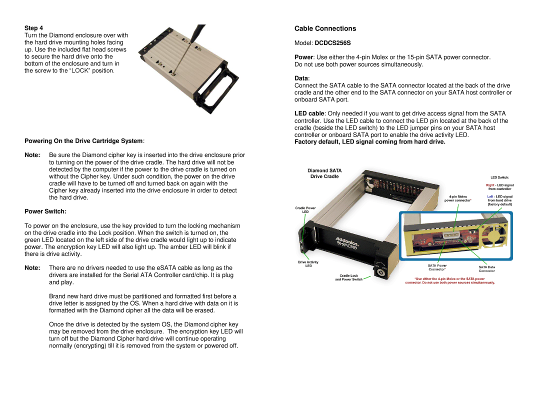
Cable Connections
Model: DCDCS256S
Power: Use either the
Data:
Connect the SATA cable to the SATA connector located at the back of the drive cradle and the other end to the SATA connector on your SATA host controller or onboard SATA port.
LED cable: Only needed if you want to get drive access signal from the SATA controller. Use the LED cable to connect the LED pin located at the back of the cradle (beside the LED switch) to the LED jumper pins on your SATA host controller or onboard SATA port to enable the drive activity LED.