Manuals
/
ADS Technologies
/
Computer Equipment
/
Personal Computer
ADS Technologies
manual
JP4 Select COM4 is RS232 or RS422/485, Description, AR-B185112
Models:
AR-B1851
1
12
41
41
Download
41 pages
19.21 Kb
9
10
11
12
13
14
15
16
Specification
IRQ Mapping Chart
Load Fail-Safe Defaults
Appendix A. Watchdog Timer
PnP/PCI Configuration Setup
Cmos Reset
Award Bios Setup
USB Port ConnectorUSB1~4
Advanced Bios Features
Power Button Setting
Page 12
Image 12
AR-B1851
User’s Guide
•
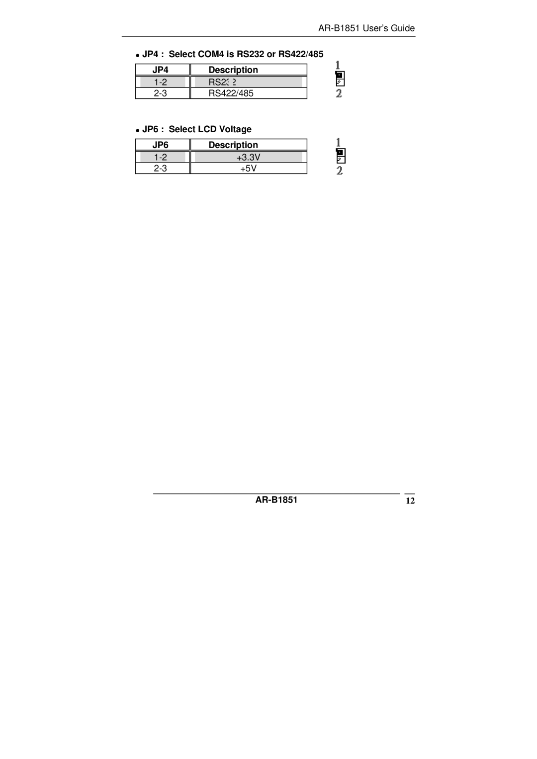
JP4 : Select COM4 is RS232 or RS422/485
JP4
1-2
2-3
Description
RS232
RS422/485
•
JP6 : Select LCD Voltage
JP6
1-2
2-3
Description
+3.3V
+5V
AR-B1851
12
Page 11
Page 13
Page 12
Image 12
Page 11
Page 13
Contents
AR-B1851
@Copyright
AR-B18512
Contents
Award Bios Setup
AR-B18514
Specifications
AR-B18515
AR-B18516
What You Have
AR-B18517
Top Placement AR-B18518
AR-B1851’s Layout
Bottom Placement AR-B18519
Power Button Setting
Cmos Reset
Jumper description
JP4 Select COM4 is RS232 or RS422/485
Description
JP6 Select LCD Voltage
AR-B185112
Ultra ATA33/66/100 IDE Disk Drive ConnectorIDE1
IDE 1 Secondary IDE Connector 44 Pins
AR-B1851
Serial PortsCOM1~4
COM2 RS-232 Serial port Pin Header
COM1 RS-232 with RS-422/485 Serial portPin Header
AR-B185114
Keyboard / Mouse ConnectorMSKB1
USB Port ConnectorUSB1~4
Fan Connector FAN1
LAN RJ45 Connector LAN1/2
FAN1 Fan Connector for CPU
LAN1/2 LAN RJ45 Connector
Compact Flash Storage Card SocketCF1
CF1 Compact Flash Storage Card Socket pin assignment
AR-B185117
VGA ConnectorVGA1
Audio ConnectorAUDIO1
VGA1 15-pin D-Sub Connector
AUDIO1 Audio Pin Header
11 8-BIT Gpio ConnectorGPIO1
Speak ConnectorSPK1
DDR Sodimm Socket J1
Lvds ConnectorLVDS1
PRN1 Parallel Port Connector
LVDS1 Lvds Interface Connector
Parallel portPRN1
Starting Setup
Using Setup
Press DEL to enter Setup
Introduction
AR-B185122
Main Menu
Options Description
IDE Adapters
AR-B185124
Cylinder0 Head0 Precomp0 Landing Zone0 Sector0
Advanced Bios Features
Apic Mode
Quick Power On Self Test
Full Screen Logo Show
Boot Display
Power Supply Type
Pwron After Power-Fail
PS/2 Mouse Function
PnP/PCI Configuration Setup
Resource controlled by
IRQ Resources
IRQ3/4/5/7/9/10/11/12/14/15 assigned to
Uart Mode Select
Peripheral
Onboard Serial Port 1/Port
Onboard Serial Port 3/Port
Onboard Parallel Port
USB Controller
USB 2.0 Controller
AR-B185130
Shutdown Temperature
PC Health
AR-B185131
Boot
First/Second/Third/Other Boot Device
AR-B185132
Save & Exit Setup
Load Optimized Defaults AR-B185133
Exit Selecting
Save to Cmos and Exit Y/N? Y
Load Fail-Safe Defaults
Exit Without Saving
Quit without saving Y/N? Y
AR-B185134
Appendix A. Watchdog Timer
Appendix B Digital I/O
AR-B185136
AR-B185137
Appendix C I/O Address Map
COM3
1DFF0000-1DFFFFFF
AR-B185140
IRQ Mapping Chart
AR-B185141
Top
Page
Image
Contents