the controller card. The controller card will

Normal Receive Path

continuously monitor the network receive T1

The receive path is non-protected and transformer

transmission service in slot 8 (i.e. standby line) for

coupled between the network and the customer. The

commands. Upon the receipt of these commands, the

receive path is monitored for in-band or ESF

controller card will initiate the T1 service switchover

bit-patterned datalink messages. The receive path

from the requested line (1 through 7) to the standby

toward the network will be terminated with a 100 ohm

line. The controller card when optioned for protect

resistor. This 100 ohm termination increases the

will conduct the following:


reliability of T1 signal recovery and minimizes

1. Monitor the incoming network signal to

crosstalk. The receive path toward the customer will

be an open termination.

determine if the protect line is operational. If the


line is operational the FAIL LED will be OFF. If

Normal Transmit Path

no signal is present, the slot 8 PROT LED will be

The transmit path is non-protected and transformer

OFF and the FAIL LED will be ON.

coupled between the network and the customer.

2. Provide a loopback to the network as long as a

Passive Mode

transmit signal is not present from the CPE. If a

The controller card can be configured to establish a

signal is placed on the slot 8 CPE transmit to the

passive transmission path by detecting a T1 signal from

network, the loopback will be released and

the customer. The transition from normal to passive

normal transmission to and from the network can

mode will require the loopback to the network removed

occur. Upon removal of the transmit signal,

and the receive path to the customer to be reconnected.

loopback will be activated.


The SCIM controller card can be locally or remotely

Passive Mode to Normal Operation

The controller card will return to normal operation by

provisioned to either enable or disable slot-switching

detection of a loss-of-signal from the customer.

capability. If a slot is protect enabled, when a switch


request for that slot is received on the protect channel,

6. PROTECT OPERATION

the slot will switch. If the slot is protect disabled, it

Protect operation is defined as the transport of data

cannot be switched.


from the network to the customer using a standby line


5. NORMAL OPERATION


connected to Slot 8. Communication between the COE

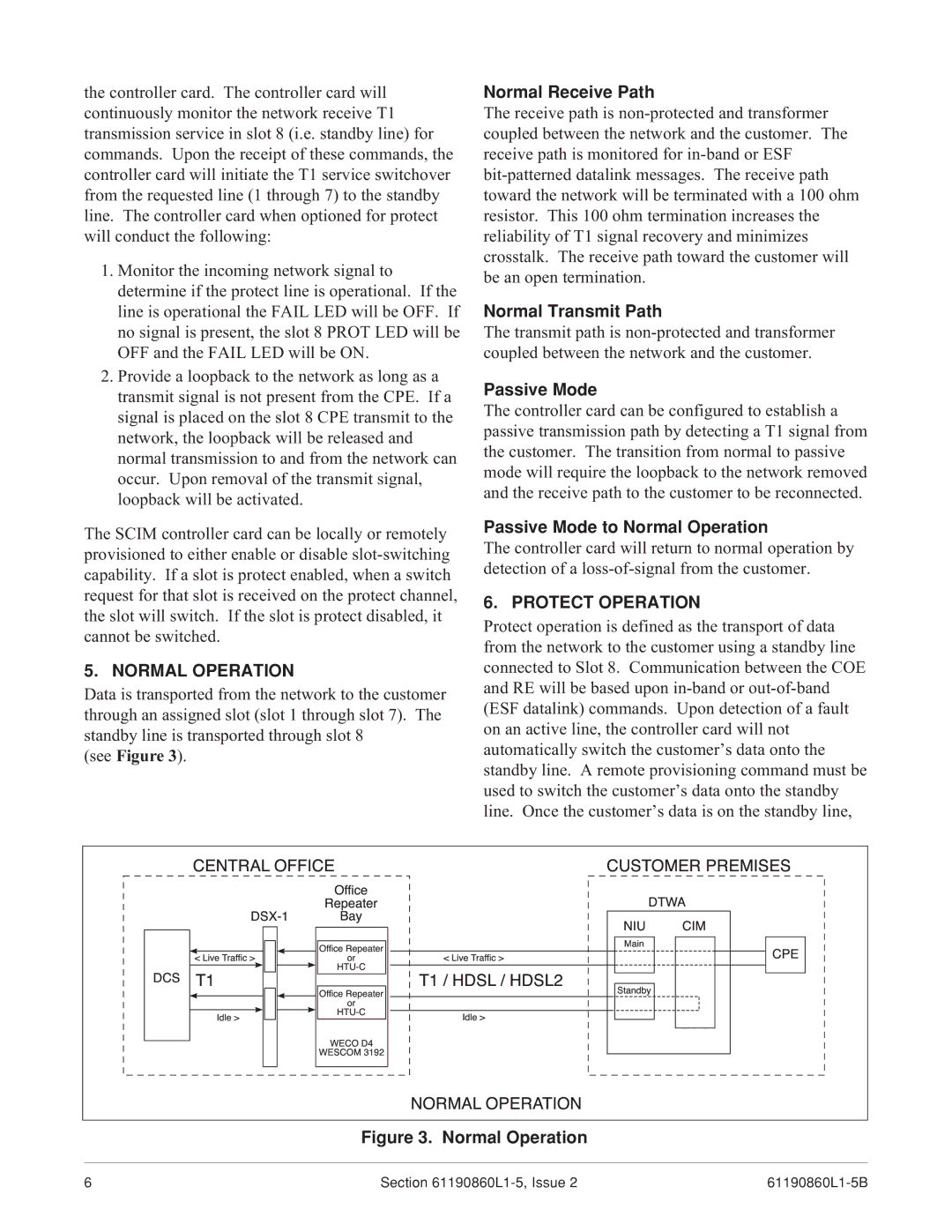
Data is transported from the network to the customer

and RE will be based upon in-band or out-of-band

(ESF datalink) commands. Upon detection of a fault


CENTRALOFFICEOffice


CUSTOMERPREMISES

through an assigned slot (slot 1 through slot 7). The

on an active line, the controller card will not

standby line is transported through slot 8

automatically switch the customer’s data onto the

(see Figure 3).


standby line. A remote provisioning command must be


DSX-1

OfficeRepeaterBayRepeater

NIUMainDTWACIM


used to switch the customer’s data onto the standby


line. Once the customer’s data is on the standby line,

DCS<T1LiveTraffic>

HTUor-C

T1/<LiveHDSLTraffic>/HDSL2

Standby

CPE

Idle>

OfficeRepeater

Idle>


WECOHTUor-CD4


WESCOM3192

NORMALOPERATION


Figure 3. Normal Operation

6

Section 61190860L1-5, Issue 2

61190860L1-5B

Page 6
Image 6
ADTRAN 1xN specifications Protect Operation, Normal Operation

1xN specifications

ADTRAN 1xN is a significant innovation in the realm of broadband network technology, designed to enhance the capacity and efficiency of data transmission in various communications infrastructures. This technology is particularly beneficial for service providers looking to upgrade their existing networks in an economically viable manner.

One of the primary features of ADTRAN 1xN is its ability to support multiple optical network terminals (ONT) from a single fiber source, which drastically reduces the amount of infrastructure required for deployment. This one-to-Many approach allows network operators to extend their service reach while minimizing the cost associated with laying down extensive fiber networks.

ADTRAN 1xN utilizes both Passive Optical Network (PON) and Active Optical Network (AON) technologies. The PON technology grants high-speed data transmission rates, accommodating several service tiers and customer demands, while the AON provides enhanced flexibility and control over data flows for network administrators. This dual-faceted approach enables operators to choose the best deployment strategy to meet specific user needs, whether in residential, commercial, or enterprise environments.

Another characteristic of this technology is its scalability. Providers can easily integrate ADTRAN 1xN into existing networks without needing extensive overhauls, allowing for easy upgrades as customer demand for service increases. This feature ensures that investments in infrastructure remain relevant and capable of handling increased data loads over time.

Additionally, ADTRAN 1xN offers robust support for various applications, including Voice over Internet Protocol (VoIP), streaming media, and cloud computing solutions. The network’s architecture effectively prioritizes data traffic to ensure quality of service, critical for users relying on real-time communications.

ADTRAN also emphasizes energy efficiency in its 1xN solutions, aligning with global sustainability initiatives. By minimizing power consumption while maximizing performance, ADTRAN not only meets operational needs but also helps service providers lower their overall environmental impact.

In conclusion, ADTRAN 1xN stands out as an inventive and flexible solution for modern broadband service providers. With its combination of advanced optical technologies, scalability, extensive application support, and commitment to energy efficiency, it represents a significant advancement in delivering high-quality, reliable internet connectivity.